
Subscribe to Our Youtube Channel
Related Manuals for Lorell LLR44312


Summary of Contents for Lorell LLR44312
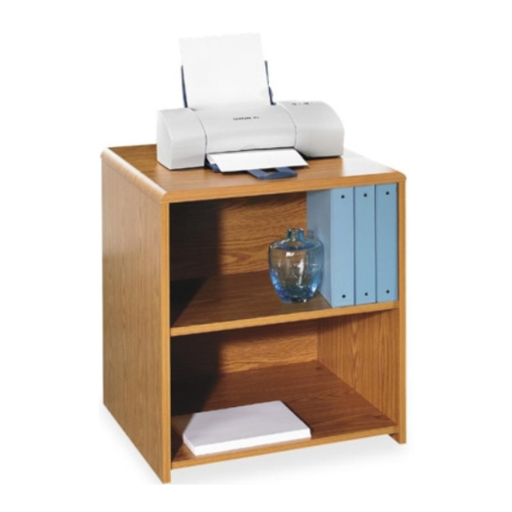
- Page 1 Printer Stand Piédestal d’imprimante Mesa para impresora LLR44312 3446D_F V4.indd 1 3446D_F V4.indd 1 3/4/11 1:14 PM 3/4/11 1:14 PM...
-
Page 2: Before You Begin
Instructions: If you are missing parts or have other concerns, please email Lorell@sprich.com or fax: 404-472-9063. Please provide the following information: 1. Full Name 2. Physical Address – do not include P.O. Box as our carriers cannot deliver to a P.O. Boxes 3. -
Page 3: Hardware Identification
HARDWARE IDENTIFICATION Page 2 of 18 3446D_F V4.indd 2 3446D_F V4.indd 2 3/4/11 1:14 PM 3/4/11 1:14 PM... -
Page 4: Panel Identification
PANEL IDENTIFICATION Page 3 of 18 3446D_F V4.indd 3 3446D_F V4.indd 3 3/4/11 1:14 PM 3/4/11 1:14 PM... - Page 5 ASSEMBLY INSTRUCTIONS Step 1 Lay Top Panel (1) on its top with the pre-drilled holes facing up. Insert the 4 Wooden Dowels (C) in the outside hole positions as shown are drawing. Tap into place with Rubber Mallet. Insert the 6 Large Cam Screws (B) into the specified positions shown utilizing a Phillips Head Screwdriver.
- Page 6 Step 5 Repeat Step 4 only utilizing the Right Side Panel (5). Step 6 With the Left Side Panel (4) laid with the screws and posts facing up, insert the Bottom Panel (3) in the position specified. Using a Phillips Screw Driver rotate the 2 Cam Locks 1/2 turn clockwise until snug.
- Page 7 Step 7 Stand unit in upright position and attach the Top Panel (1) into the holes specified. Using a Phillips Screw Driver rotate the 2 Cam Locks 1/2 turn clockwise until snug. (DO NOT OVER TIGHTEN). Attach 6 Cam Lock Caps (E) to the Large Cam Locks that secure the top to the unit.
-
Page 8: Avant De Commencer
Instructions: Veuillez nous faire parvenir un courriel à lorell@sprich.com ou un fax à : 404-472-9063, s’il vous manque des pièces ou que vous éprouvez d’autres inquiétudes. Veuillez fournir l’information suivante : 1. Nom complet 2. Adresse physique – ne donnez pas votre boîte postale car nos livreurs ne peuvent pas livrer à une boîte postale 3. - Page 9 IDENTIFICATION DE LA QUINCAILLERIE Page 8 of 18 3446D_F V4.indd 8 3446D_F V4.indd 8 3/4/11 1:14 PM 3/4/11 1:14 PM...
- Page 10 IDENTIFICATION DES PANNEAUX Page 9 of 18 3446D_F V4.indd 9 3446D_F V4.indd 9 3/4/11 1:14 PM 3/4/11 1:14 PM...
-
Page 11: Instructions D'assemblage
INSTRUCTIONS D’ASSEMBLAGE Étape 1 Déposez le panneau supérieur (1) sur sa partie du dessus avec les trous pré-percés dirigés vers le haut. Insérez les 4 chevilles de bois (C) dans les positions des trous extérieurs comme montré sur le dessin. Tapez celles-ci en place à... - Page 12 Étape 5 Répétez seulement l’étape 4 en utilisant le panneau latéral de droite (5). Étape 6 Pendant que le panneau latéral de gauche (4) est couché avec les vis et les poteaux dirigés vers le haut, insérez le panneau inférieur (3) dans la position spécifiée. À...
- Page 13 Étape 7 Soulevez l’unité dans sa position debout et fixez le panneau supérieur (1) dans les trous spécifiés. À l’aide d’un tournevis Phillips, tournez les 2 verrous à came 1/2 tour dans le sens horaire jusqu’à ce qu’ils soient appuyés. (NE SERREZ PAS TROP FORT) Insérez 6 capuchons (E) de verrou à...
-
Page 14: Antes De Iniciar
Instrucciones: Si le faltan partes o tiene alguna pregunta, escriba un mensaje de correo electrónico a Lorell@sprich.com o envíe un fax al 404-472-9063. Recuerde incluir la siguiente información: 1. Nombre completo 2. Domicilio. No incluye apartado postal debido a que nuestros distribuidores no pueden hacer entregas a un apartado postal. - Page 15 IDENTIFICACIÓN DE TORNILLERÍA Y ACCESORIOS Page 14 of 18 3446D_F V4.indd 14 3446D_F V4.indd 14 3/4/11 1:14 PM 3/4/11 1:14 PM...
- Page 16 IDENTIFICACIÓN DE LOS TABLEROS Page 15 of 18 3446D_F V4.indd 15 3446D_F V4.indd 15 3/4/11 1:14 PM 3/4/11 1:14 PM...
-
Page 17: Instrucciones De Ensamble
INSTRUCCIONES DE ENSAMBLE Paso 1 Coloque el Tablero superior (1) sobre su parte superior con los orificios previamente perforados hacia arriba. Inserte 4 Clavijas de madera (C) en los orificios del exterior como se muestra en el dibujo. Asegure en su lugar con el Martillo de goma. - Page 18 Paso 5 Repita el Paso 4 utilizando ahora el Tablero derecho (5). Paso 6 Con el Tablero izquierdo (4) con los tornillos y postes hacia arriba, inserte el Tablero inferior (3) en la posición especificada. Utilizando un Desarmador Phillips, gire los 2 Seguros de ajuste media vuelta en el sentido de las manecillas del reloj hasta que ajusten.
- Page 19 Paso 7 Coloque la unidad en la posición vertical y una el Tablero superior (1) en los orificios especificados. Utilizando un Desarmador Phillips, gire los 2 Seguros de ajuste media vuelta en el sentido de las manecillas del reloj hasta que ajusten. (NO APRIETE DE MÁS) Coloque las 6 Tapas de los Seguros (E) en los Seguro de ajuste largos de la unidad.
Need help?
Do you have a question about the LLR44312 and is the answer not in the manual?
Questions and answers