
Related Manuals for Waters ACQUITY CH-A

Summary of Contents for Waters ACQUITY CH-A
- Page 1 ACQUITY Column Heater - Active Overview and Maintenance Guide 715005052 Copyright © Waters Corporation 2019 Version 02 (previously released as Rev.B) All rights reserved...
-
Page 2: General Information
This document is believed to be complete and accurate at the time of publication. In no event shall Waters Corporation be liable for incidental or consequential damages in connection with, or arising from, its use. For the most recent revision of this document, consult the Waters website (www.waters.com). -
Page 3: Customer Comments
We seriously consider every customer comment we receive. You can reach us at tech_comm@waters.com. Contacting Waters Contact Waters with enhancement requests or technical questions regarding the use, transportation, removal, or disposal of any Waters product. You can reach us via the Internet, telephone, fax, or conventional mail. Waters contact information Contacting medium... -
Page 4: Safety Hazard Symbol Notice
Safety hazard symbol notice symbol indicates a potential hazard. Consult the documentation for important information about the hazard and the appropriate measures to prevent and control the hazard. Considerations specific to the Column Heater-Active Warning: To prevent burn injuries, set the column temperature to Off, and then allow the column compartment and its components to cool for 60 minutes before touching them. -
Page 5: Operating The Device
For compliance with the Waste Electrical and Electronic Equipment Directive (WEEE) 2012/19/EU, contact Waters Corporation for the correct disposal and recycling instructions For indoor use only December 4, 2019, 715005052 Version 02 (previously released as Rev.B) -
Page 6: Audience And Purpose
This guide is intended for individuals who install, operate, and maintain the column heater with the active pre-heater (CH-A). Intended use of the CH-A Waters designed the CH-A for use in liquid chromatography (LC) applications. The CH-A is not intended for use in diagnostic applications. Calibrating To calibrate LC systems, adopt acceptable calibration methods using at least five standards to generate a standard curve. -
Page 7: Emc Considerations
EMC considerations Canada spectrum management emissions notice This class A digital product apparatus complies with Canadian ICES-001. Cet appareil numérique de la classe A est conforme à la norme NMB-001. ISM classification: ISM group 1 class B This classification has been assigned in accordance with CISPR 11 Industrial Scientific and Medical (ISM) instrument requirements. -
Page 8: Table Of Contents
Table of contents General information .......................ii Copyright notice ............................. ii Trademarks ............................ii Customer comments..........................iii Contacting Waters..........................iii Safety considerations..........................iii Safety hazard symbol notice ......................iv Considerations specific to the Column Heater-Active ..............iv FCC radiation emissions notice...................... iv Canada spectrum management emissions notice................iv Equipment misuse notice ....................... - Page 9 2.5.2 Enabling the leak sensor ..................... 64 2.5.3 Controlling the column compartment ................... 65 2.6 Responding to a leak-sensor alarm ....................65 3 Maintenance ......................68 3.1 Contacting Waters Technical Service ................... 68 3.2 Recommended maintenance schedule..................69 3.2.1 Recommended CH-A routine maintenance schedule............69 3.3 Spare parts............................ 69 3.4 Safety and handling ........................
- Page 10 A.1.1 Specific warnings ........................ 90 A.2 Notices............................91 A.3 Bottles Prohibited symbol ......................92 A.4 Required protection ........................92 A.5 Warnings that apply to all Waters instruments and devices ............92 A.6 Warnings that address the replacement of fuses................96 A.7 Electrical symbols ......................... 98 A.8 Handling symbols ......................... 99 B Specifications......................100...
-
Page 11: Overview
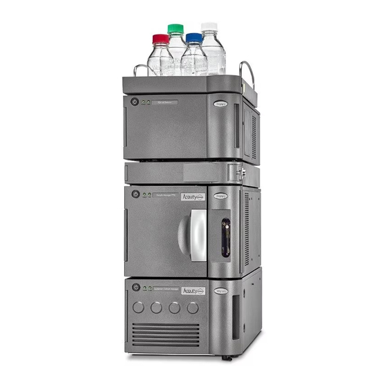
Overview The Column Heater-Active (CH-A) is a column heating module that manages and maintains the column temperature for ACQUITY Arc systems, ACQUITY Arc Bio systems, and ACQUITY UPLC systems, including ACQUITY UPLC H-Class Series, ACQUITY UPLC H-Class Bio Series, and ACQUITY UPLC I-Class Series systems. - Page 12 Figure 1–1: CH-A module in ACQUITY UPLC system stack Detector CH-A module Sample manager Solvent manager For mass spectrometry (MS) applications, you can mount the column heater assembly on an external bracket on the right-hand side of the chassis, reducing the distance to the inlet probe of a mass spectrometer.
-
Page 13: Major Components
Figure 1–2: CH-A module mounted on external bracket CH-A module in extended column compartment installation 1.1 Major components The following figure shows the major components of a CH-A module. Figure 1–3: Compartment interior December 4, 2019, 715005052 Version 02 (previously released as Rev.B) Page 13... -
Page 14: Column Heater
A receptacle on the column heater module receives the column's eCord fob, if one is present. The eCord records column manufacturing and usage data that is accessible from the Waters console. For more information about the recorded column data, see "eCord... -
Page 15: Aph Operation
1.2.2 APH operation The standard APH assembly provides thermal equilibration by heating the incoming mobile phase and sample to the specified column temperature before it enters the column. The assembly uses an electric heating element to directly heat the column-inlet tubing. The rapid heating, low-volume design reduces gradient delay and extra-column band-spreading. -
Page 16: Column Configurations
Restriction: You cannot use the APH assembly and the passive column-stabilizer assembly simultaneously; choose the preheater type that best suits your application. Figure 1–5: Typical column stabilizer assembly Long, flat compression screw fitting for connecting to valve assembly Column-stabilizer inlet tubing #2 locking cap nut #1 hex compression fitting Column-stabilizer gasket... -
Page 17: Ecord Technology
Table 1–1: Supported column configurations Quantity Description Column length = 150 mm; column ID = 4.6 mm, maximum; Column guard or column in-line filter = 20 mm, maximum; 1.4 eCord technology ACQUITY UPLC columns include an eCord column chip that tracks the usage history of the column. -
Page 18: Preparation And Operation
Preparation and operation Before you prepare a CH-A module for operation, prepare the sample manager and solvent manager. Before running samples, you must prepare the CH-A module for operation. To do so, perform these tasks: • Install the CH-A module onto the system stack. •... - Page 19 leakage from the detector or drip tray located above the column compartment to pass through the integrated leak management system within the CH-A rear enclosure and into the sample manager's upper drip tray. Required tools and materials • T20 TORX driver •...
- Page 20 Figure 2–2: Installing the retainer bracket onto the sample manager's top cover CH-A-to-SM retainer bracket Sample manager's top cover TORX screw Cutout in bracket As shown in the figure above, position the retainer bracket so that the openings in the bracket align with the openings in the sample manager's top cover, and the cutout in the bracket faces the sample manager's rear panel.
-
Page 21: Extended Column Compartment Installation
Figure 2–3: Securing the CH-A to the sample manager Sample manager's rear panel studs extended through slots in the CH-A back plate Opening in the CH-A back plate aligned with the threaded opening in the center of the sample manager's rear panel From the CH-A start-up kit, obtain the TORX screw with nylon washer. -
Page 22: Preparing The Ch-A For Installation With The Ms-Bracket Kit
• Detach the column heater from the rear enclosure installed on the sample manager chassis. • Install the MS-extension bracket onto the CH-A rear enclosure. • Attach the column-heater housing onto the MS-extension bracket. • Install the MS-bracket drip tray onto the column-heater housing. •... - Page 23 Required tools and materials • Chemical-resistant, powder-free gloves • Protective eyewear • 1/4-inch open-end wrench • Needle-nose pliers • Flat-blade screwdriver • T20 TORX driver To prepare the CH-A for installation with the MS-bracket kit: Stop any running mobile phase. Power-off the sample manager.
- Page 24 Remove the APH assembly and retainer, as follows: Remove the APH assembly from the retainer in the column compartment. Figure 2–5: Removing the APH assembly APH assembly APH retainer clip Using the needle-nose pliers, gently compress the top and bottom sides of the APH retainer and withdraw it from the control port.
- Page 25 11. Slide the column-compartment tray to the right and insert the APH retainer into the left- hand APH control port. Figure 2–7: Sliding the column-compartment tray Column-compartment tray 12. Using the T-20 TORX driver, remove the TORX screw from the right-hand side of the column compartment, behind the eCord receptacle.
- Page 26 Figure 2–9: Detaching the column heater from its rear enclosure Column heater Rear enclosure 14. Using the flat-blade screwdriver, loosen the two retaining screws, and then remove the CH- A interconnect cable's 25-pin connector from the D-sub receptacle on the rear of the column heater.
- Page 27 Figure 2–11: CH-A–to–SM retainer bracket Location for front, left-hand foot of the CH-A chassis CH-A–to–SM retainer bracket installed on sample manager's top cover • If the retainer bracket is already installed and the front, left-hand foot of the CH-A rear enclosure is seated in the retainer bracket on the sample manager's top cover, no further preparation steps are necessary.
- Page 28 Figure 2–12: Removing the TORX screw TORX screw in sample manager's rear panel 19. Carefully lift and remove the CH-A rear enclosure from the sample manager. 20. From the CH-A start-up kit, locate the CH-A–to–SM retainer bracket and TORX screw. Figure 2–13: Installing the retainer bracket on the sample-manager chassis CH-A–to–SM retainer bracket Sample manager's top cover...
- Page 29 22. Insert the TORX screw through the opening in the bracket and into the threaded opening in the sample manager's top cover, and then tighten it using the T20 TORX driver to secure the retainer bracket to the sample-manager chassis. 23.
-
Page 30: Installing The Ms-Extension Bracket And Column-Heater Housing
2.2.2 Installing the MS-extension bracket and column-heater housing The MS-bracket kit contains all of the components that you need to configure the column heater in its extended position. Follow these instructions to install the bracket and column-heater mounting hardware. Required tools and materials •... - Page 31 To install the MS-extension bracket and column-heater housing: Insert the tab on the left-hand side of the MS-extension bracket into the slot in the left-hand side of the CH-A rear enclosure that is installed on the sample manager chassis. Figure 2–15: Inserting the MS-extension bracket tab into the CH-A rear enclosure Tab on MS-extension bracket Slot inside CH-A rear enclosure While holding the MS-extension bracket inserted in the left-hand side of the housing, route...
- Page 32 Press the right-hand side of the MS-extension bracket into the rear enclosure cutout until it seats. Important: Ensure that the CH-A interconnect cable remains in the slot as you guide the tab into the cutout. If the cable slips out of the slot, it can prevent the bracket from seating fully into the rear enclosure.
- Page 33 Short side of hinge attached to MS-extension bracket Long side of hinge attached to column-heater housing Swing the column-heater housing, aligning it with the front of the mass spectrometer, and examine the positioning to determine if the column-heater housing is at the correct height for the mass spectrometer inlet.
- Page 34 Two TORX screws Height-adjustment bracket MS-extension bracket Using two TORX screws, attach the hinge assembly on the column-heater housing to the height-adjustment bracket, using the set of holes that reposition the column- heater housing at the correct height for the mass spectrometer inlet. Reinspect the positioning height and, if necessary, adjust the height of the column- heater housing by removing the hinge from the height-adjustment bracket, and then reattaching it using different holes.
- Page 35 Figure 2–22: Aligning and inserting the leak sensor in the MS-bracket drip tray Slot in column-heater housing for routing leak-sensor cable Leak-sensor T-bar Slot in leak-sensor reservoir Drain tubing 12. Route the leak-sensor cable through the slot in the column-heater housing. 13.
-
Page 36: Installing The Ch-A In The Extended Position
2.2.3 Installing the CH-A in the extended position After preparing the CH-A and installing the MS-extension bracket and column-heater housing, follow these instructions for completing the extended column compartment installation. Warning: To avoid personal contamination with biologically hazardous, toxic, and corrosive materials, wear chemical-resistant, powder-free gloves when performing this procedure. - Page 37 Tighten the cable clamp nut with the 4-mm wrench. Insert the tab on the left-hand side of the column heater into the slot on the left-hand side of the housing. Hold the left-hand side of the column heater into the slot and guide the eCord tab, on the right-hand side, into the cutout in the column-heater housing.
-
Page 38: Column Compartment Plumbing Connections
D-sub receptacle on rear of column heater If you installed the leak sensor in the MS-bracket drip tray, insert the leak-sensor cable's connector into the receptacle located on the rear, left-hand side of the column heater. Figure 2–26: Leak-sensor receptacle on the rear, left-hand side of the column heater Leak-sensor receptacle 10. -
Page 39: Installation Recommendations For Fittings
Warning: To prevent burn injuries, set the column temperature to Off, and then allow the column compartment and its components to cool for 60 minutes before touching them. Monitor the column compartment's internal temperature to ensure that all components are cool. Warning: Observe Good Laboratory Practice (GLP) at all times, particularly when working with hazardous materials. - Page 40 2.3.1.1 Assembling new fittings For metallic (SST or MP35N) fitting and tubing assemblies with ferrules not previously assembled or set to tubing, you must mark the compression screw and connection port and ensure that the two marks line up when you tighten them. Warning: To avoid eye injury, use eye protection when performing this procedure.
- Page 41 First-use tightening: 2.3.1.2 Stainless steel (gold-plated) fitting with long flats and two-piece stainless steel ferrule (V-detail) First use Long flats Compression screw Two-piece stainless steel ferrule Tighten the fitting finger-tight plus an additional 3/4-turn using a 1/4-inch open-end wrench. Tip: To prevent band spreading, ensure that the tubing is fully bottomed in the connection port before you tighten the compression screw.
- Page 42 Reinstalled Long flats Compression screw Two-piece stainless steel ferrule Tighten the fitting finger-tight plus as much as an additional 1/6-turn using a 1/4-inch open-end wrench. Reinstalled tightening 2.3.1.3 Stainless steel (gold-plated) fitting with short flats and 2-piece stainless steel ferrule (V-detail) First use Short flats Compression screw...
- Page 43 Tip: To prevent band spreading, ensure that the tubing is fully bottomed in the connection port before you tighten the compression screw. First use tightening Reinstalled Short flats Compression screw 2-piece stainless steel ferrule Tighten the fitting finger-tight plus as much as an additional 1/6-turn using a 1/4-inch open-end wrench.
- Page 44 2.3.1.4 One piece PEEK fitting Figure 2–27: First use or reinstalled Compression screw Tighten the fitting finger-tight. Tips: • You can also use the column-gripping tool when tightening this fitting. • To prevent band spreading, ensure that the tubing is fully bottomed in the connection port before tightening the fitting.
- Page 45 Figure 2–28: APH outlet fitting first use or reinstalled #1 knurled compression fitting #2 locking cap nut Back-locking PEEK ferrule Figure 2–29: Column-stabilizer outlet fitting first use or reinstalled #1 hex compression fitting #2 locking cap nut Back-locking PEEK ferrule December 4, 2019, 715005052 Version 02 (previously released as Rev.B) Page 45...
- Page 46 Figure 2–30: Legacy fitting first use or reinstalled Hex compression fitting Locking cap nut Back-locking or standard PEEK ferrule To tighten the fitting: Loosen the cap nut from the compression fitting. Slide the compression fitting together with the ferrule into the inlet of the column (or the in- line filter).
-
Page 47: Installing The Aph Assembly
Compression fitting Column gripping tool Column Tip: If you are operating the system at, or close to, its maximum system operating pressure limit and the fitting is a hex, use the 1/2-inch open-end wrench to tighten the compression fitting an additional 1/8- to 1/6-turn. Tighten the cap nut onto the compression fitting. - Page 48 • 1/2-inch open-end wrench • APH assembly For a standard CH-A configuration, the tubing for the column compartment's APH assembly extends from the sample manager's injection valve outlet. It continues through the APH assembly (installed in the right-hand control port of the column compartment) to the column, and terminates at the detector inlet.
- Page 49 Figure 2–33: Flow path for extended CH-A configuration fitted with an APH assembly A P H COLUMN APH assembly tubing connected to sample-manager injection valve outlet APH assembly installed in left-hand control port Column inlet Column outlet Column-outlet-to-mass-spectrometer-inlet tubing Note: The column stabilizer is not supported in the MS extended position.
- Page 50 Figure 2–34: Connection diagrams for a CH-A fitted with an APH assembly Sample manager Injection Column Detector valve Sample manager Injection Filter Column Detector valve Table 2–2: Legend Identifier Description Length Material APH assembly 32 cm (12.5 inches) SST or MP35N (Bio) with .004-inch ID tubing that connects the sample manager's...
- Page 51 Table 2–2: Legend (continued) Identifier Description Length Material Stainless steel (gold- SST (gold-plated plated) fitting with screw) short flats and two- piece stainless steel ferrule Dual-threaded fitting with locking cap nut 10-32 one-piece PEEK PEEK fitting To install the APH assembly: Unpack the new APH assembly.
- Page 52 Column trough APH inlet tubing Fluidics compartment door hinge Loosen the #2 locking cap nut on the APH before assembling the column or in-line filter. Note: For instructions on how to install the column in-line filter, see Installation recommendations for fittings.
-
Page 53: Installing The Column Stabilizer Assembly
APH assembly and retainer from the column-heater compartment and install the column-stabilizer assembly. Notice: Waters does not recommend using the column stabilizer with normal-phase solvents, including the following and other similar solvents: tetrahydrofuran (THF), methylene chloride, ethyl acetate, chloroform, hexane, heptane, octane,... - Page 54 Figure 2–37: Flow path for a CH-A fitted with a column stabilizer COLUMN Column-stabilizer-inlet tubing connected to sample manager injection valve outlet Column stabilizer mounted in column-compartment trough Column inlet Column outlet Column-outlet-to-detector-inlet tubing December 4, 2019, 715005052 Version 02 (previously released as Rev.B) Page 54...
- Page 55 Figure 2–38: Connection diagrams for a CH-A fitted with a column stabilizer Sample manager Injection Column Detector valve Column Stabilizer Sample manager Injection Filter Column Detector valve Column Stabilizer Table 2–3: Legend Identifier Description Length Material Column stabilizer Column-stabilizer 32 cm (12.5 inches) assembly that connects the sample manager's injection-...
- Page 56 Table 2–3: Legend (continued) Identifier Description Length Material Stainless steel (gold- SST (gold-plated plated) fitting with screw) short flats and two- piece stainless steel ferrule Dual-threaded fitting with locking cap nut 10-32 one-piece PEEK PEEK fitting To install the column stabilizer: Stop any running mobile phase.
- Page 57 Using the needle-nose pliers, gently compress the top and bottom sides of the APH retainer and withdraw it from the control port. Figure 2–40: Removing the APH retainer clip Gently compress the retainer at these locations to remove it from the control port Remove the O-ring retainer from the inlet end of the column-stabilizer-inlet tubing and connect the inlet tubing to port 6 of the sample manager injection valve.
- Page 58 Figure 2–42: Pulling the column fitting away from the column stabilizer #1 hex compression fitting #2 locking cap nut Column stabilizer retainer 11. Align the two Phillips screws to the threaded holes in the column trough, and then press the column stabilizer into the trough. 12.
-
Page 59: Connecting The Power And Signal Cable
2.4 Connecting the power and signal cable The CH-A module receives power from the sample manager. Communications and control signals for the CH-A module are provided through the 25-pin, D-series, sub-connector (D-sub) receptacle on the rear panel of the sample manager. Thus, to connect the CH-A module to the electricity source and operate the CH-A module, you must connect the D-sub interconnect cable connector that exits through the CH-A rear chassis panel to the mated connector on the sample manager, and then power-on the sample manager. -
Page 60: Installing The Column Module Switch Box
2.4.1 Installing the Column Module Switch Box With the optional Waters Column Module Switch Box, you can physically connect a CH-A and a 30-cm column module (either a CH-30A or a 30-cm CHC) to the SM-FTN and switch the electrical control of the column modules via the SM-FTN console. - Page 61 Using the T20 TORX driver, loosen the left T20 TORX screw and remove the center T20 TORX screw from the sample manager's rear panel. Figure 2–44: Loosening and removing the TORX screws Left T20 TORX screw Center T20 TORX screw Replace the center T20 TORX screw with the longer T20 TORX screw provided in the Column Module Switch Box kit.
- Page 62 Left T20 TORX screw Center T20 TORX screw Connect the interconnect cables to the switch box before placing the switch box into the mounting bracket: Insert the CH-A interconnect cable connector into the D-sub receptacle labeled CH- A on the switch box and, using the flat-blade screwdriver, tighten the two retaining screws to secure the connector.
- Page 63 30CM CH-A CH-30A or 30-cm CHC interconnect cable CH-A interconnect cable SM-FTN interconnect cable If you connected the 30-cm CHC, power-on the module using the power on/off switch on its lower, right-hand side. 10. Power-on the sample manager. 11. Verify that the switch box is operational: From the SM-FTN console, navigate to Sample Manager FTN >...
-
Page 64: Column Compartment Configuration And Control
2.5 Column compartment configuration and control Before you can operate a column heater with active pre-heating, you must configure it in the console to ensure that the column heater is ready to operate according to your application. You control the column heater via the console or instrument method in the chromatography data software. -
Page 65: Controlling The Column Compartment
To control the CH-A module, enter its compartment temperature settings using the sample manager control panels or method editor in the chromatography data software. For details, refer to the Waters online Help. Recommendation: When sample and column temperature are important to an application, in addition to specifying explicit temperature set points in the method, specify appropriate temperature limits. - Page 66 Required tools and materials • Chemical-resistant, powder-free gloves • Protective eyewear • Cotton swabs • Nonabrasive, lint-free wipes To restore the leak sensor to service: In the console, select System from the system tree. Click Control > Leak Sensors. Determine which of the system's leak sensors detected a leak. If the message reads Leak Detected (Column), power-off the sample manager.
- Page 67 10. Roll up a nonabrasive, lint-free wipe and use it to absorb the liquid from the leak-sensor reservoir and its surrounding area. 11. With a cotton swab, absorb any remaining liquid from the corners of the leak-sensor reservoir. 12. Align the sensor's T-bar with the slot in the side of the leak-sensor reservoir and slide the leak sensor into place.
-
Page 68: Maintenance
Waters console Help. 3.1 Contacting Waters Technical Service If you are located in the USA or Canada, report malfunctions or other problems to Waters Technical Service (800-252-4752). From elsewhere, phone the Waters corporate headquarters in Milford, Massachusetts (USA) or contact your local Waters subsidiary. -
Page 69: Recommended Maintenance Schedule
As necessary or paper dampened with water 3.3 Spare parts To ensure that your system operates as designed, use only Waters Quality Parts. Visit www.waters.com/wqp for information about Waters Quality Parts, including how to order them. 3.4 Safety and handling Observe these warning and caution advisories when you perform maintenance operations on your system. -
Page 70: Configuring Maintenance Warnings
You can minimize unexpected failures and unscheduled downtime during important work. For information explaining how to specify maintenance warnings, consult the Waters console Help. 3.6 Replacing the leak sensor Leak detection for a standard, stack-mounted CH-A is supported by a leak sensor located behind the sample manager door, in the upper drip tray. - Page 71 To replace the leak sensor: Power-off the sample manager. Depending on the configuration of the column heater leak-sensor you are replacing, do as follows: • If the leak sensor is in the sample manager's upper drip tray, follow the instructions for replacing the leak sensor in the ACQUITY UPLC Sample Manager - Flow Through Needle PLUS Series Overview and Maintenance Guide.
- Page 72 Figure 3–2: Rear view of column heater showing D-sub receptacle D-sub receptacle on rear of column heater Press down on the tab to detach the leak-sensor connector from the receptacle located on the rear, left-hand side of the column heater. Figure 3–3: Leak-sensor receptacle on the rear, left-hand side of the column heater Receptacle for the leak-sensor connector 10.
- Page 73 Figure 3–4: Leak sensor in MS-bracket drip tray Removing leak-sensor cable from slot in column-heater housing Leak-sensor serrations Leak-sensor T-bar Slot in leak-sensor reservoir 12. Remove the leak-sensor cable from the slot in the column-heater housing. 13. Grasp the leak sensor by its serrations, and pull upward on it, to remove it from its reservoir.
- Page 74 15. Unpack the new leak sensor. 16. Align the leak-sensor T-bar with the slot in the leak-sensor reservoir, and press the new leak sensor into the slot so that the prism sits in the reservoir. 17. Insert the leak-sensor cable through the slot in the column heater housing. 18.
-
Page 75: Removing A Column Connected To An Aph Assembly
26. Power-on the sample manager. 27. In the console, select Sample Manager FTN > Control > Reset module, to reset the sample manager. 28. In the console, enable the leak sensor, to activate its leak-detection capability. 3.7 Removing a column connected to an APH assembly During scheduled preventive maintenance or when changing methods, you can remove the column from the column compartment before replacing it with a new column of the same or different type. - Page 76 Figure 3–6: Removing the APH assembly APH assembly APH retainer clip Disconnect the column outlet fitting. Loosen the #2 locking cap nut on the APH assembly before removing the column assembly. Place the column gripping tool onto the column. While holding the column with the column gripping tool, loosen the #1 knurled compression fitting and remove the column assembly.
-
Page 77: Replacing The Aph Assembly
Compression fitting Column gripping tool Column To install the replacement column, see Column compartment plumbing connections. 3.8 Replacing the APH assembly Before replacing the APH assembly in the CH-A, ensure that you obtained the correct replacement assembly for the system type, the application (SST or MP35N), and the length of the APH-inlet tubing (32 cm or 47 cm) (12.5 inches or 18.5 inches) that you intend to use. - Page 78 To replace the APH assembly: Stop any running mobile phase. Open the fluidics compartment door of the sample manager. Using the 1/4-inch open-end wrench, disconnect the long, flat compression-screw end of the APH assembly from port 6 of the sample manager injection valve. After allowing sufficient time for cooling, open the column compartment door.
- Page 79 Tip: Place the column gripping tool onto the column to loosen the dual-threaded fitting. Set aside the APH assembly for discarding. 10. Unpack the new APH assembly. Note: For instructions on replacing the APH retainer clip, see Replacing the APH retainer clip.
-
Page 80: Replacing The Aph Retainer Clip
17. Start the mobile phase, examine the assembled components for leaks, and then tighten the fittings, if necessary. 18. Close the column compartment door and ensure that the door is clasped shut. 3.9 Replacing the APH retainer clip If you have a legacy APH installed in your system and you ordered a new APH assembly, you may need to replace the retainer clip. -
Page 81: Removing A Column Connected To A Column-Stabilizer Assembly
Press the retainer clip at these locations and push it into the control port. Apply force to the four corners of the retainer clip to ensure that each of them has snapped into place. 3.10 Removing a column connected to a column-stabilizer assembly During scheduled preventive maintenance or when changing methods, you can remove the column from the column compartment before replacing it with a new column of the same or a... -
Page 82: Replacing The Column Stabilizer Assembly
Figure 3–12: Pull the column fitting away from the column stabilizer #1 hex compression fitting #2 locking cap nut Column stabilizer Disconnect the column outlet fitting. Loosen the #2 locking cap nut on the column-stabilizer assembly before removing the column assembly. Use the 1/2-inch open-end wrench to loosen the #1 hex compression fitting and remove the column assembly. - Page 83 Warning: To prevent burn injuries, set the column temperature to Off, and then allow the column compartment and its components to cool for 60 minutes before touching them. Monitor the column compartment's internal temperature to ensure that all components are cool. Warning: To avoid personal contamination with biologically hazardous or toxic compounds, wear clean, chemical-resistant, powder-free gloves when performing this procedure.
- Page 84 Note: For installation instructions, see Assembling new fittings. 11. Route the column-stabilizer-inlet tubing behind the hinge of the fluidics compartment door in the sample manager and into the slot that leads to the column trough. Figure 3–13: Routing the column-stabilizer-inlet tubing Column trough Column-stabilizer-inlet tubing Fluidics compartment door hinge...
-
Page 85: Replacing The Ferrule On The Column-Inlet Fitting
#1 hex compression fitting #2 locking cap nut Column stabilizer retainer 14. Align the two Phillips screws to the threaded holes in the column trough, and then press the column-stabilizer into the trough. 15. Use the #1 Phillips screwdriver to tighten the screws. Note: Alternate tightening between the two screws to ensure that the column-stabilizer is secure and sits flat against the trough. - Page 86 Required tools and materials • Chemical-resistant, powder-free gloves • Protective eyewear • Replacement ferrule To replace the ferrule on the column fitting: Unscrew the #2 locking cap nut from the #1 knurled compression fitting. Figure 3–15: Unscrewing cap nut from fitting #1 knurled compression fitting #2 locking cap nut Slide the #1 knurled compression fitting off the tubing.
- Page 87 Figure 3–17: Removing ferrule from fitting #1 knurled compression fitting Ferrule (captive ferrule shown) Discard the used ferrule. Install the new ferrule on the fitting. Slide the #1 knurled compression fitting and ferrule onto the tubing. Figure 3–18: Sliding fitting and ferrule onto tubing Tubing #1 knurled compression fitting Note:...
-
Page 88: Cleaning The Exterior Of The Equipment
Figure 3–19: Screwing cap nut onto fitting #1 knurled compression fitting #2 locking cap nut 3.13 Cleaning the exterior of the equipment Warning: To avoid electric shock: • Ensure that the electrical power to the equipment is interrupted. • When cleaning the surface of the equipment, apply water to a cloth, and then wipe the instrument or device. -
Page 89: A Safety Advisories
Heed all warnings when you install, repair, or operate any Waters instrument or device. Waters accepts no liability in cases of injury or property damage resulting from the failure of individuals to comply with any safety precaution when installing, repairing, or operating any of its instruments or devices. -
Page 90: Specific Warnings
(Risk of high-pressure gas release.) A.1.1 Specific warnings A.1.1.1 Burst warning This warning applies to Waters instruments and devices fitted with nonmetallic tubing. Warning: To avoid injury from bursting, nonmetallic tubing, heed these precautions when working in the vicinity of such tubing when it is pressurized: •... -
Page 91: Notices
A.1.1.2 Biohazard warning The following warning applies to Waters instruments and devices that can process biologically hazardous materials. Biologically hazardous materials are substances that contain biological agents capable of producing harmful effects in humans. Warning: To avoid infection from blood-borne pathogens, inactivated microorganisms, and other biological materials, assume that all biological fluids that you handle are infectious. -
Page 92: Bottles Prohibited Symbol
Use eye protection when performing this procedure. Requirement: Wear clean, chemical-resistant, powder-free gloves when performing this procedure. A.5 Warnings that apply to all Waters instruments and devices When operating this device, follow standard quality-control procedures and the equipment guidelines in this section. - Page 93 Advertencia: cualquier cambio o modificación efectuado en esta unidad que no haya sido expresamente aprobado por la parte responsable del cumplimiento puede anular la autorización del usuario para utilizar el equipo. 警告: 未经有关法规认证部门明确允许对本设备进行的改变或改装,可能会使使用者丧 失操作该设备的合法性。 警告: 未經有關法規認證部門允許對本設備進行的改變或修改,可能會使使用者喪失操作 該設備的權利。 경고: 규정 준수를 책임지는 당사자의 명백한 승인 없이 이 장치를 개조 또는 변경할 경우, 이...
- Page 94 Warnung: Bei der Arbeit mit Polymerschläuchen unter Druck ist besondere Vorsicht angebracht: • In der Nähe von unter Druck stehenden Polymerschläuchen stets Schutzbrille tragen. • Alle offenen Flammen in der Nähe löschen. • Keine Schläuche verwenden, die stark geknickt oder überbeansprucht sind. •...
- Page 95 圧力のかかったポリマーチューブを扱うときは、注意してください。 • 加圧されたポリマーチューブの付近では、必ず保護メガネを着用してください。 • 近くにある火を消してください。 • 著しく変形した、または折れ曲がったチューブは使用しないでください。 • 非金属チューブには、テトラヒドロフラン(THF)や高濃度の硝酸または硫酸などを流さないでくださ い。 • 塩化メチレンやジメチルスルホキシドは、非金属チューブの膨張を引き起こす場合があり、その場 合、チューブは極めて低い圧力で破裂します。 This warning applies to Waters instruments fitted with nonmetallic tubing or operated with flammable solvents. December 4, 2019, 715005052 Version 02 (previously released as Rev.B) Page 95...
-
Page 96: Warnings That Address The Replacement Of Fuses
Warning: The user shall be made aware that if the equipment is used in a manner not specified by the manufacturer, the protection provided by the equipment may be impaired. Avertissement : L’utilisateur doit être informé que si le matériel est utilisé d’une façon non spécifiée par le fabricant, la protection assurée par le matériel risque d’être défectueuses. - Page 97 Avertissement : pour éviter tout risque d'incendie, remplacez toujours les fusibles par d'autres du type et de la puissance indiqués sur le panneau à proximité du couvercle de la boite à fusible de l'instrument. Warnung: Zum Schutz gegen Feuer die Sicherungen nur mit Sicherungen ersetzen, deren Typ und Nennwert auf den Tafeln neben den Sicherungsabdeckungen des Geräts gedruckt sind.
-
Page 98: Electrical Symbols
警告: 为了避免火灾,应更换“维护步骤”一章的“更换保险丝”一节中介绍的相同类 型和规格的保险丝。 警告: 為了避免火災,更換保險絲時,應使用「維護步驟」章節中「更換保險絲」所指 定之相同類型與規格的保險絲。 경고: 화재의 위험을 막으려면 유지관리 절차 단원의 “퓨즈 교체” 절에 설명된 것과 동 일한 타입 및 정격의 제품으로 퓨즈를 교체하십시오. 警告: 火災予防のために、ヒューズ交換ではメンテナンス項目の「ヒューズの交換」に記載されているタ イプおよび定格のヒューズをご使用ください。 A.7 Electrical symbols The following electrical symbols and their associated statements can appear in instrument manuals and on an instrument’s front or rear panels. -
Page 99: Handling Symbols
A.8 Handling symbols The following handling symbols and their associated statements can appear on labels affixed to the packaging in which instruments, devices, and component parts are shipped. Symbol Description Keep upright! Keep dry! Fragile! Use no hooks! Upper limit of temperature Lower limit of temperature Temperature limitation December 4, 2019, 715005052 Version 02 (previously released as Rev.B) -
Page 100: B Specifications
Specifications The reproducibility of the specifications presented in this document depends on the conditions in individual laboratories. Contact the Waters Technical Service organization for additional information about specifications. B.1 CH-A physical specifications Attribute Specification Height 7.6 cm (3 inches) Width 34.3 cm (13.5 inches) -
Page 101: A Electrical Specifications
B.3 CH-A electrical specifications Attribute Specification Pollution degree Normal (IPXO) Moisture protection Supply voltage, nominal 24 Vdc Line frequency 0 Hz Power consumption 84 W a. Pollution Degree 2 – A measure of pollution on electrical circuits that can produce a reduction of dielectric strength or surface resistivity.
Need help?
Do you have a question about the ACQUITY CH-A and is the answer not in the manual?
Questions and answers