Table of Contents
Advertisement
Quick Links
Advertisement
Table of Contents

Related Manuals for Routline SUPERFLY MANTAS 28


Summary of Contents for Routline SUPERFLY MANTAS 28
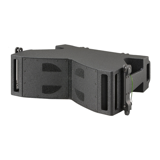
- Page 1 SUPERFLY MANTAS 28 RIGGING MANUAL...
- Page 2 Superfly Mantas 28 Rigging Manual Version: 2.0 Release date: 2022/10/07 © Outline 2022. All rights reserved. Refer all servicing to qualified personnel, through your Outline dealer. OUTLINE S.R.L. Tel.: +39 030.3581341 www.outline.it Via Leonardo da Vinci, 56 Fax +39 030.3580431 25020 Flero (Brescia) Italy info@outline.it...
-
Page 3: Table Of Contents
CONTENTS 1. SAFETY REGULATIONS ....................4 1.1. DISPOSAL OF WASTE MATERIALS ....................... 4 1.2. CONFORMITY AND WARRANTY ......................4 2. COMPONENTS OVERVIEW ..................... 5 2.1. LOAD CAPACITY ............................ 5 2.2. FRAME BAR SPECIFICATIONS ......................6 2.3. INTEGRATED HARDWARE OF LINE ARRAY ELEMENTS ..............8 2.4. -
Page 4: Safety Regulations
1. SAFETY REGULATIONS Welcome to the Outline World! • respect the limits set for the mechanical parts We suggest you take your time to reading this imposed by Outline OpenArray2 software as manual in order get to know this product in depth described in this manual;... -
Page 5: Components Overview
2. COMPONENTS OVERVIEW To perform all the rigging steps correctly, it is by OpenArray2 projects, will ensure compliance with essential to know the components that make all the established and certified parameters to always part of the sound reinforcement system and their guarantee public safety during the executive phases characteristics. -
Page 6: Frame Bar Specifications
2.2. FRAME BAR SPECIFICATIONS FRM1-AL630 Superfly / Mantas28 is a rigging frame bar approved and certified for these two line array elements that share the same integrated hardware. Below you will find the specifications of the frame bar: • Weight…………………………….………………..21.5 kg •... - Page 7 FRM1-AL630 is equipped with four brackets (two holes for fastening the hoist(s), as calculated by front and two rear ones), easy to mount and fasten to OpenArray2. the line array elements. Its load beam has 20 hanging The shackle should be fastened to the hanging holes indicated by the software.
-
Page 8: Integrated Hardware Of Line Array Elements
2.3. INTEGRATED HARDWARE OF LINE ARRAY ELEMENTS Similar to the rigging frame hardware, the Superfly/Mantas28 elements also have a simple but very efficient hardware structure. These hardware elements are made of ultra-light aluminium and are designed, approved and certified to support the established loads. -
Page 9: Locking Pins
The front of the cabinet (figure 3) has non-adjustable brackets on both sides, complementary to the rear ones. The example in Figure 3 shows a first element fastened to the rigging frame and a second element ready to be fastened. Learn more about the various steps in Chapter 4. -
Page 10: Hardware Inspection
2.5. HARDWARE INSPECTION It is of utmost importance to periodically check the Check that the locking pins close correctly, integrity of the entire structure of the hardware, both which means that the two steel balls come out of the line array elements and of the rigging frame. completely outside the locking pin body. -
Page 11: Open Array 2 - Pre-Rigging
3. OPEN ARRAY 2 - PRE-RIGGING OpenArray2 is proprietary Outline software for 3D for installing the line array systems, showing the simulation of electro-acoustic events. impossibility of installation in the event of the load- This tool is able to guide system engineers through bearing limits of the mechanical components being correct set-up procedure from an acoustic and exceeded, and other data necessary for the installation... - Page 12 figure 6 Warning! The installation will only be possible if the mechanical check with “Open Mechanics” has given a positive result. If the word ‘Out of range!’ appears, the necessary changes must be made in order to bring the figure 7 mechanical stress values within the permitted limits (they could be: reassess the overall inclination of the array in case the center of gravity is out of range, as in...
- Page 13 Based on what stated in chap. 2.1, as depicted in figure 9, when setting 20 Superfly elements only hanging holes #5 thru #16 are available as the Notice statement. The final weight of the array (array mass) will be different from the declared 760 kg (20 x Superfly cabinets, 38 kg each).
-
Page 14: Rigging Procedure
4. RIGGING PROCEDURE 4.1. PREPARATION Once the necessary motors have been arranged according to the project and the elements are out of their flightcases, it is possible to proceed with the rigging. However, we suggest you follow the steps described below to do everything with ease. - Page 15 3. lock the bars with the locking pins using one of the corresponding holes, according to the chosen degree (figure 14); figure 14 4. align the link bars with the rails of the next 5. once the angles for each couple of line array array element and fasten them with the locking elements are ready to be flown, proceed with pin in the “Default”...
-
Page 16: Preparation Of The Frame Bar
4.1.2. PREPARATION OF THE FRAME BAR It is advisable to prepare the rigging frame immediately to be flown together with the first two elements of the array, to make the job easier for the staff: 1. free the rear brackets of the frame by simply lifting the movable bracket that will be triggered, remaining stationary thanks to the automatic locking system (figure 16);... - Page 17 4. align the rear brackets of the rigging frame with the rails of the fist line array element and lock with the pins in the “Default” position. To simplify the procedure it could be of help to lift the rigging frame with one hand, keeping it steady with a foot, and insert the pin with the other hand (figure 20).
-
Page 18: Assembling
4.2. ASSEMBLING Once the preparation phases have been completed, the array can be lifted starting with the first two elements and then adding the remaining pairs, integrating any supplementary accessories (spansets, cables, safety locks etc. - chap. 4.3): 1. lift the first two elements already fastened to the rigging frame and the hoist, keeping the front brackets of the second element free (this will make the following step easier - figure 24);... - Page 19 3. using the hoist(s), lift the array from the trolley at a suitable height to simplify the following procedure (figure 29); figure 28 4. at this point, fasten the front brackets of the first three elements that are now flown. Help yourself with both hands to lift the element as shown in figure 30, to be able to insert the locking pin in the hole (figure 31).
-
Page 20: Intermediate Phase
4.3. INTERMEDIATE PHASE When the first four elements are flown, before continuing it could be necessary to add the following accessories: a spanset for rigging the cables (with a shackle or simply knotting to the frame. Please, note that attacching the spanset to the frame causes a different inclination of the array) (figure 33);... -
Page 21: Final Phase
4.4. FINAL PHASE Proceed with flying the remaining elements till you complete the array, making sure that all the locking pins are positioned correctly. The last steps to follow are: tie the cables together to create a well-ordered bundle as the array goes up; once reached the necessary height, fix the array with the ropes to regulate the vertical and horizontal inclination according to the project;... -
Page 22: Derigging
4.5. DERIGGING For the reverse process the steps to follow are exactly the opposite to those just described. After removing the ropes and the secure lock, when starting to lower the array, it can be useful to consider the following points: place the trolleys under the array so that the elements can be put on them in couples and remove the locking pins from the front brackets of the last... -
Page 23: Ground Stack Configuration
4.6. GROUND STACK CONFIGURATION For a stack array configuration it is necessary to follow a procedure where the rigging frame and the array elements are literally upside down. Always keeping in mind the indications given by the OpenArray2 software, proceed as follows: 1. - Page 24 4. mount the element upon the frame upside down (180°) to have the rear bracket looking upwards; 5. secure the front brackets and then the rear ones, remembering that the whole procedure will be the same but to be done on the contrary (figure 44).
-
Page 25: Transport And Storage
5. TRANSPORT AND STORAGE When transporting the system it is advisable: • to move the elements as shown in figure 48 to avoid accidents (figure 47) • although resistant, avoid placing any excessive loads on the closed flight cases containing the array elements;... -
Page 26: Notes
6. NOTES OUTLINE S.R.L. Tel.: +39 030.3581341 www.outline.it Via Leonardo da Vinci, 56 Fax +39 030.3580431 25020 Flero (Brescia) Italy info@outline.it... - Page 27 NOTES OUTLINE S.R.L. Tel.: +39 030.3581341 www.outline.it Via Leonardo da Vinci, 56 Fax +39 030.3580431 25020 Flero (Brescia) Italy info@outline.it...
- Page 28 Outline carries out on-going research for product improvement. New materials, manufacturing methods and design upgrades are introduced to existing products without prior notice as a routine result of this philosophy. For this reason, any current Outline product may differ in some aspect from its description, but will always equal or exceed the original design specifications unless otherwise stated.
Need help?
Do you have a question about the SUPERFLY MANTAS 28 and is the answer not in the manual?
Questions and answers