Table of Contents
Advertisement
Quick Links
Advertisement
Table of Contents

Subscribe to Our Youtube Channel
Related Manuals for Minarik RG5500U


Summary of Contents for Minarik RG5500U
- Page 1 RG5500U Isolated-Input, Four-Quadrant, Regenerative SCR Drive...
- Page 2 Drives and its Divisions make no warranty of any kind with respect to this material, including, but not limited to, the implied warranties of its merchantability and fitness for a given purpose. Minarik Drives and its Divisions assume no responsibility for any errors that may appear in this manual and make no commitment to update or to keep current the information in this manual.
- Page 3 Follow sound maintenance procedures. It is possible for a drive to run at full speed as a result of a component failure. Minarik strongly recommends the installation of a master switch in the main power input to stop the drive in an emergency.
-
Page 4: Table Of Contents
Contents Specifications ......... .1 Dimensions . - Page 5 Application Notes ........40 Connection to other Minarik devices .......40 Optional speed adjust potentiometer connections .
- Page 6 Figure 2. RG5500U Dimensions ........3...
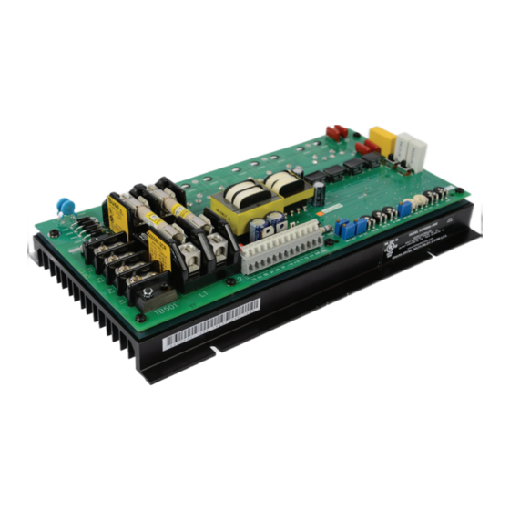
- Page 7 The RG5500U is a full-wave, four-quadrant regenerative drive which provides smooth motoring and braking torque for SCR brush-type DC motors. The RG5500U controls motors from 1 through 5 Hp for single or bi-directional variable speed.
-
Page 8: Figure 1. Four Quadrant Operation
Figure 1. Four Quadrant Operation... -
Page 9: Specifications
Specifications Model Number RG5500U Type Open Chassis AC Line Voltage 115 VAC or 230 VAC, ±10%, 50Hz or 60 Hz, single phase Line Fuse Rating 40 A (Buss Type SC–40 or equivalent) Field Fuse Rating 3 A, fast acting Horsepower Range @ 90 VDC Output 1 –... - Page 10 Specifications Recommended Speed Adjustment Potentiometer † 5 Kohms to 20 Kohms Input Impedance Voltage Signal (S0 to S2) 25 Kohms Voltage Signal (S0 to HV) 125 Kohms Current Signal, 1–5 mADC 1 Kohms Current Signal, 4–20 mADC 235 ohms Current Signal, 10–50 mADC 100 ohms Speed Regulation (% of base speed) Armature Feedback...
-
Page 11: Dimensions
Dimensions 8.00 [203] 12.13 [308] 0.19 [5] 2.06 [52] 6.30 [160] 2.60 [66] 0.12 [3] 6.89 [175] FOUR (4) MOUNTING SLOTS 0.19 [5] X 3.0 [8] DEEP ALL DIMENSIONS IN INCHES [MILLIMETERS] Figure 2. RG5500U Dimensions... -
Page 12: Installation
Installation Warning Do not install, remove, or rewire this equipment with power applied. Failure to heed this warning may result in fire, explosion, or serious injury. Read and understand the Safety Warnings on page i before attempting installation. The chassis must be earth grounded. Use a star washer beneath the head of at least one of the mounting screws to penetrate the anodized chassis surface and to reach bare metal. -
Page 13: Wiring
Installation Wiring Warning Do not install, remove, or rewire this equipment with power applied. Failure to heed this warning may result in fire, explosion, or serious injury. Read and understand the Safety Warnings on page i before attempting installation. Circuit potentials are at 115 or 230 VAC above ground. To prevent the risk of injury or fatality, avoid direct contact with the printed circuit board or with circuit elements. -
Page 14: Shielding Guidelines
As a general rule, Minarik recommends shielding of all conductors. If it is not practical to shield power conductors, Minarik recommends shielding all logic-level leads. If shielding logic leads is not practical, the user should twist all logic leads with themselves to minimize induced noise. -
Page 15: Speed Adjust Potentiometer Installation
Installation Speed adjust potentiometer installation Warning Be sure that the potentiometer tabs do not make contact with the potentiometer enclosure. Grounding the input will cause damage to the drive. Install the circular insulating disk between the mounting panel and the 10K ohm speed adjust potentiometer (see Figure 3). Mount the speed adjust potentiometer through a 0.38-inch (10 mm) hole with the hardware provided. -
Page 16: Fusing
Installation Fusing RG5500U drives have two 40A line fuses and one 3A field fuse installed. These fuses do not have to be resized. Replacement fuses may be ordered from your local Minarik Drives distributor. See Replacement Parts section on Page 54 for the fuse part numbers. -
Page 17: Cage-Clamp Terminal Block
Installation Cage-clamp terminal block Logic connections to RG5500U are made to a cage-clamp terminal block. Refer to figure 4 for terminal block wiring procedure. 1. Press down on the lever arm using a small screwdriver. 2. Insert wire into the wire clamp. -
Page 18: Connections
200% of motor nameplate current and 250 volts. Motor connections Minarik drives supply motor voltage from A1 and A2 terminals. It is assumed throughout this manual that, when A1 is positive with respect to A2, the motor will rotate clockwise (CW) while looking at the output shaft protruding from the front of the motor. -
Page 19: Speed Adjust Potentiometer Connections
Installation Speed adjust potentiometer connections The motor can operate in one direction (unidirectional) or two directions (bidirectional) depending on how the speed adjust potentiometer is connected to the drive. Connect the speed adjust potentiometer as shown in Figure 6(a) on Page 13 for bidirectional operation. The motor does not operate when the wiper is in the center position. -
Page 20: Figure 5. Rg5500U Connections
SPEED ADJUST FU504 1 2 3 POT 10K OHMS POWER SWITCH 115 or 230 VAC INPUT OPTIONAL EARTH TACH-GENERATOR GROUND * MOTOR FIELD SHUNT-WOUND MOTORS ONLY * Connection shown for 100 VDC or 200 VDC fields. Figure 5. RG5500U Connections... -
Page 21: Figure 6. Speed Adjust Potentiometer Connections
Installation (a) BIDIRECTIONAL TB502 S3 S2 SPEED ADJUST POT 10K OHM (b) UNIDIRECTIONAL (FWD) (c) UNIDIRECTIONAL (REV) TB502 TB502 S3 S2 S3 S2 SPEED SPEED ADJUST POT ADJUST POT 10K OHM 10K OHM Figure 6. Speed Adjust Potentiometer Connections... -
Page 22: Field Output
Using tachogenerator feedback will improve speed regulation from approximately 1% of motor base speed to approximately 0.1% of motor base speed. RG5500U drives can use tachogenerators rated from 7 VDC per 1000 RPM to 50 VDC per 1000 RPM. Connect the tachogenerator to terminals T1 (+) and T2 (-) of terminal block TB502. -
Page 23: Signal Follower (Optional)
Installation Signal follower (optional) Instead of using a speed adjust potentiometer, the drive may be wired to follow an external voltage or current input signal. See Figure 7 for signal follower connections and Figure 12 on Page 20 for DIP switch settings. TB502 TB502 CS S3... -
Page 24: Polarity Reversal Switch (Optional)
Installation Polarity reversal switch (optional) To reverse the output voltage polarity without changing the input polarity, connect DIR to COM. A single-pole, single-throw switch can be used as a polarity reversal switch. Close the switch to reverse the output voltage polarity. Open the switch to return the output voltage back to its original polarity. -
Page 25: And -15 Terminals (Optional)
Do not short the +15 and -15 VDC terminals for any reason. Shorting these terminals may damage the drive. If you use relays, industrial PCs, or PLCs, Minarik recommends programming a delay before switching from one mode / direction to the other. -
Page 26: Disable / Enable Terminals
Installation DISABLE / ENABLE terminals Warning Do not short the +24 and COM terminals for any reason. Shorting these terminals may damage the drive. Each drive is assembled with the DISABLE / ENABLE terminals set to ENABLE (jumper on INH and -24V terminals). See Figure 10 for connections. -
Page 27: Slide Switches (Sw501-Sw504)
Installation Slide switches (SW501–SW504) Set all slide switches to their proper setting before applying power (see Figure 11). SW501 and SW502: SW503: set to 115 or 230 to match set to 90 or 180 to match the the AC line voltage. maximum armature voltage. -
Page 28: Dip Switches (Sw505)
Installation DIP switches (SW505) Set SW505 to correspond to the voltage input signal or current input signal being used. See Figure 11 for dip switch location. Use one of the four settings shown in Figure 12. Set all DIP switches ON when a speed adjust CFVS potentiometer is used. -
Page 29: Operation
Operation Warning Dangerous voltages exist on the drive when it is powered. BE ALERT. High voltages can cause serious or fatal injury. Before applying power • Verify that no conductive material is present on the printed circuit board. • Set all switches to their proper settings. •... -
Page 30: Startup
Operation Startup Uni-directional Operation 1. Set the speed adjust potentiometer to minimum (full CCW). 2. Apply AC line voltage. 3. Slowly turn the speed adjust potentiometer clockwise (CW). If a voltage or current signal is used, slowly increase the voltage or current signal. The motor will accelerate as the potentiometer is turned CW, or the voltage or current signal is increased. -
Page 31: Voltage Follower
Operation Voltage Follower 1. If the drive is following a voltage signal, set the voltage signal to 0 VDC. 2. Slowly increase the voltage signal. The motor will accelerate as the signal is increased. Continue until the desired speed is reached. -
Page 32: Starting And Stopping Methods
(FWD TQ and REV TQ on regenerative drives) are still active while the drive is in inhibit mode. NOTE: Minarik strongly recommends the installation of an emergency stop switch. The switch contacts should be rated at a minimum of 250 volts and 200% of maximum motor current. -
Page 33: Automatic Restart Upon Power Restoration
Operation Automatic restart upon power restoration All drives automatically run to set speed when power is applied. Wiring a switch or latching relay onto the DISABLE / ENABLE terminal block allows you to apply AC line voltage to the drive without engaging the power circuitry. -
Page 34: Figure 13. Regen Brake Terminals
Operation Minarik Drives offers two accessory plug harnesses for use with the REGEN BRAKE switch: Minarik ® Part Number Description 201-0024 Inhibit plug with 18 in. (46 cm) wires 201-0079 Inhibit plug with 36 in. (91 cm) wires Twist inhibit plug wires and separate them from other power-carrying wires or sources of electrical noise. -
Page 35: Decelerate To Minimum Speed
Operation Decelerate to minimum speed The circuit shown in Figure 14 may be used to decelerate a motor to a minimum speed. Closing the switch between S2 and S0 decelerates the motor from set speed to a minimum speed determined by the MIN OUT trimpot setting. If the MIN OUT trimpot is set full CCW, the motor decelerates to zero speed when the switch between S2 and S0 is closed. -
Page 36: Calibration
Calibration Warning Dangerous voltages exist on the drive when it is powered. When possible, disconnect the voltage input from the drive before adjusting the trimpots. If the trimpots must be adjusted with power applied, use insulated tools and appropriate personal protection equipment. BE ALERT. High voltages can cause serious or fatal injury. -
Page 37: Minimum Speed Out (Min Out)
Calibration MINIMUM SPEED OUT (MIN OUT) The MIN OUT setting determines the minimum speed when the speed adjust potentiometer, voltage input signal, or current input signal is set for minimum speed. It is factory set to zero speed. The minimum speed feature applies only when the drive is operating in unidirectional mode. -
Page 38: Forward Acceleration (Fwd Acc)
Calibration FORWARD ACCELERATION (FWD ACC) The FWD ACC setting determines the time it takes the motor to ramp to either a higher speed in the forward direction or a lower speed in the reverse direction, within the limits of available torque. -
Page 39: Ir Compensation (Ir Comp)
Calibration IR COMPENSATION (IR COMP) The IR COMP (also known as Regulation) setting determines the degree to which motor speed is held constant as the motor load changes. It is factory set for optimum motor regulation. Recalibrate the IR COMP setting when using a lower current rated motor. -
Page 40: Forward Torque (Fwd Tq)
Continuous operation beyond this rating may damage the motor. If you intend to operate beyond the rating, contact your Minarik representative for assistance. The FWD TQ setting determines the maximum torque for accelerating and driving the motor in the forward direction. It also sets the maximum torque for decelerating the motor in the reverse direction. -
Page 41: Reverse Torque (Rev Tq)
Continuous operation beyond this rating may damage the motor. If you intend to operate beyond the rating, contact your Minarik representative for assistance. The REV TQ setting determines the maximum torque for accelerating and driving the motor in the reverse direction. It also sets the maximum torque for decelerating in the forward direction. -
Page 42: Figure 15. Typical Fwd Tq, Rev Tq, And Ir Comp Settings
Calibration 5 HP 2 HP 180 VDC 90 VDC 24 ADC 20 ADC FWD TQ REV TQ IR COMP FWD TQ REV TQ IR COMP 1 1/2 HP 3 HP 90 VDC 180 VDC 15 ADC 13.7 ADC FWD TQ REV TQ IR COMP FWD TQ... -
Page 43: Deadband (Db)
Calibration DEADBAND (DB) The deadband trimmer potentiometer determines the time that will elapse between the application of current in one direction before current is applied in the opposite direction. It also affects the resistance that a motor has to changes in shaft position at zero speed by applying AC voltage to the motor armature. -
Page 44: Tachogenerator (Tach)
Calibration TACHOGENERATOR (TACH) For use with tachogenerator feedback only Calibrate TACH only when a tachogenerator is used. TACH, like IR COMP, determines the degree to which motor speed is held constant as the motor load changes. To calibrate the TACH trimpot: 1. -
Page 45: Current Signal Offset
Contact your Minarik representative before attempting adjustment, as improper calibration may have unpredictable results. The RG5500U has a factory-set offset to guarantee stability in a stopped motor. To calibrate CURR SIG OFFSET: 1. Ensure that input power is turned OFF. -
Page 46: Input Adjust (Input Adj)
Calibration INPUT ADJUST (INPUT ADJ) The INPUT ADJ trimpot scales the voltage input signal. Voltage Input Signal Calibration 1. Verify that DIP switch 1 (CFVS) on SW505 is ON. Set all other switches on SW505 to OFF. (see Figure 12 on page 20) 2. - Page 47 Calibration Current Input Signal Calibration 1. Verify that the correct DIP switch is ON (see Figure 12 on page 20). 2. Apply the minimum current input signal. 3. Adjust the MIN OUT trimpot until the motor runs at the desired minimum speed. 4.
-
Page 48: Application Notes
Application Notes Connection to other Minarik devices RG5500U DLC600 DRIVE DIGI-LOK CONTROL Figure 17. RG5500U Connection to Minarik DLC600... -
Page 49: Figure 18. Rg5500U Connection To 200-0386A Limit Switch Logic Board
See figure 18 for RG5500UA connections to the 200-00386A limit switch logic board. For more information on Minarik’s limit switch logic board, refer to User’s Manual 250-0222 or the Minarik Product Catalog. -
Page 50: Optional Speed Adjust Potentiometer Connections
Application Notes Optional speed adjust potentiometer connections FWD-REV switch Use a single pole, two-position switch with a single speed adjust potentiometer to plug reverse a motor (Figure 19). The MIN OUT setting is in effect for either direction. Note: High currents exist when plug reversing a motor. -
Page 51: Fwd-Min Spd-Rev Switch
Application Notes FWD-MIN SPD-REV switch Use a single pole, three position switch with a single speed adjust potentiometer to stop a motor between reversals (Figure 20). Set the switch to the center position to decelerate the motor to minimum speed. Note: High currents exist when plug reversing a motor. -
Page 52: Independent Adjustable Speeds
Application Notes Independent adjustable speeds Connect two speed adjust potentiometers with a single pole two position switch to select between two independent speeds shown in the forward direction (Figure 21). The speed adjust potentiometers can be mounted at two separate operating stations. Note: Total parallel resistance should be 10K ohms. -
Page 53: Independent Forward And Reverse Speeds
Application Notes Independent forward and reverse speeds Connect two speed adjust potentiometers to select between independent forward and reverse speeds (Figure 22). 10K OHMS 10K OHMS FORWARD REVERSE Figure 22. Independent Forward and Reverse Speeds... -
Page 54: Independent Forward And Reverse Speeds With A Fwd-Stop-Rev Switch
Application Notes Independent forward and reverse speeds with a FWD- STOP-REV switch Use a single pole, three position switch to stop the motor when the switch is in the center position (Figure 23). 10K OHMS 10K OHMS FORWARD STOP REVERSE Figure 23. -
Page 55: Troubleshooting
5. Check that line fuses FU501 and FU502 are properly sized and not blown. 6. Check that field fuse FU503 is 3A and not blown. For additional assistance, contact your local Minarik® distributor, or the factory direct: (800) MINARIK or (815) 624-5959 (815) 624-6960 fax... - Page 56 Troubleshooting Problem Possible Suggested Causes Solutions Field fuse blows 1. Field fuse is the 1. Verify that the fuse wrong size. is 3 A. 2. Motor field is 2. Check if the motor shorted field is shorted to to ground. ground.
- Page 57 2. Check motor cable armature is shorted and armature for to ground. shorts. 3. Field circuit is 3. Send drive to open. Minarik Repair Department. 4. Nuisance tripping 4. Add a blower to caused by a cool the drive combination of components;...
- Page 58 Troubleshooting Problem Possible Suggested Causes Solutions Line fuse is not 1. Speed adjust 1. Increase the speed blown, but the potentiometer, adjust motor does not run voltage input potentiometer, signal, or current voltage, or current input signal set to setting. zero speed.
- Page 59 Troubleshooting Problem Possible Suggested Causes Solutions Line fuse is not 6. Drive is in current 6. Verify that motor is blown, but the limit. not jammed. motor does not run Increase FWD TQ (con’t) or REV TQ setting. They may be set too low.
- Page 60 Troubleshooting Problem Possible Suggested Causes Solutions Motor will not 1. MAX OUT setting 1. Increase MAX reach the desired is too low. OUT setting. speed 2. INPUT ADJ setting 2. Recalibrate is too low. INPUT ADJ setting. 3. IR COMP setting is 3.
- Page 61 Troubleshooting Problem Possible Suggested Causes Solutions Motor does not 1. Bad switch 1. Check switch reverse connection to DIR connection to DIR and COM. and COM. 2. Reversing circuit 2. Check reversing not working circuit by shorting properly. DIR to COM with jumper wire.
-
Page 62: Replacement Parts
Troubleshooting Replacement Parts Replacement parts are available from Minarik Drives and its distributors for this drive series. Table 2. Replacement Parts Model No. Symbol Description Minarik P/N RG5500U C502, 503 470 uF, 50 V Capacitor 011-0056 C510 .47 uF, 250 V Capacitor... - Page 63 NOTES...
- Page 64 NOTES...
-
Page 65: Unconditional Warranty
C. Limitations of Liability In the event of any claim for breach of any of Minarik Drives obligations, whether express or implied, and particularly of any other claim or breech of warranty contained in Paragraph A, or of any other warranties, express or implied, or claim of liability that... - Page 66 MINARIK DRIVES 14300 De La Tour Drive South Beloit, IL 61080 Phone: (800) MINARIK or (815 ) 624-5959 Fax: (815) 624-6960 www.minarikdrives.com Document number 250–0225, Revision 5 Printed in the U.S.A – 05/13 $11.00 U.S.A. – $12.00 Outside U.S.A.
Need help?
Do you have a question about the RG5500U and is the answer not in the manual?
Questions and answers