Advertisement
Quick Links
User Manual
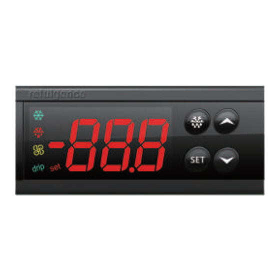
ECS-974neo Temperature Controller
1. Product overview
ECS-974neo is a universal standard temperature controller.
2.Display and operation panel
Mounting size: 71 x 29 mm
3. Technical parameters
1)Temperature measuring range: -50℃~99℃(Only when sensor calibration value is set to 0)
2)Resolution: 0.1℃/1℃ settable
3)Accuracy: ±1℃(-40℃~50℃), ±2℃(others)
4)Temperature control range: -50℃~99℃
5)Power supply: 220 VAC±10 %, 50/60Hz; Overall power consumption: <3W
6)Input port: Cabinet sensor, Evaporator sensor
7)Output port: Cooling/Defrost/Fan
8)Protection grade of front panel: IP65
9)Operating ambient temperature:0℃~55℃
10)Storage temperature:-25℃~75℃
11)Storage humidity: 20%~85% (non-condensing)
4. LED
LED
Symbol
Setting
set
Cooling
Defrost
Fan
drip
Drip
5.Parameter table
Menu
No.
Description
Item
0
SEt
Temperature set-point
1
PA1
Administrator menu password
2
diF
Differential
3
HSE
Higher SEt. Max possible set-point
4
LSE
Lower SEt. Min possible set-point
Product size: 78.5 x 34.5 x 74 mm
Status
Meaning
ON
Set administrator menu
ON
Cooling starts.
OFF
Cooling stops.
Flash
Cooling delays.
ON
Defrost starts.
OFF
Defrost stops.
ON
Fan starts.
OFF
Fan stops.
ON
Dripping.
OFF
Drip stops.
Setting range
User menu
LSE~HSE
Administrator menu
00~250
0.1℃~30.0℃
SEt~99.0
-50.0~SEt
Menu
No.
Item
5
Ont
Ont: On time (compressor). Compressor activation time in the event of faulty probe.
OFt: OFF time (compressor). Compressor stop time in the event of a faulty probe.
If Ont=0, the compressor is off.
6
OFt
If Ont≠0 and OFt=0, the compressor is always on.
If Ont≠0 and OFt≠0, the compressor functions in duty cycle mode per Ont/OFt.
Delay (after power) OFF. Delay after switch off; the indicated time must elapse
7
dOF
between switch-off of the compressor relay and the successive switch-on.
Delay Output (from power) On. Delay time in activating the outputs after switch-on
8
OdO
of the controller or after a power failure.
Defrost type:0 = electric defrost;
9
dty
1 = reverse cycle defrost (hot gas);
2 = Free defrost (compressor hot).
10
Defrost interval time. Interval between the start of two successive defrost
dit
operations.
Defrost Counting type. Selection of count mode for the defrost interval.
0 = compressor operating hours;
11
dCt
1= fixed time interval;
2 = compressor stop hours.
12
dOH
Defrost offset hour. Start-of-defrost delay time from startup of controller.
13
dEt
Defrost endurance time. Defrost time-out; dEt=0, defrost is disabled.
14
H42
Whether to enable evaporator sensor: y=yes; n=no
15
dSt
Defrost stop temperature
Defrost (at) Power On. Determines if at the start-up the controller must enter
16
dPO
defrosting (if the temperature measured allows this operation).
y = yes; n = no.
17
FSt
Fan stop temperature
18
FAd
Fan activation differential
19
Fdt
Fan delay time. Delay time in activating fans after a defrost operation.
20
dt
Drainage time. Dripping time
Defrost fan disable. Allows to select the evaporator probes exclusion during defrost.
21
dFd
y = yes; n = no.
Fan Compressor OFF. Allows selecting compressor fans lock OFF (switched off). y =
22
FCO
fans activated; n = fans off
23
HAL
High Alarm differential
24
LAL
Low Alarm differential
Power-on Alarm Override. Alarm exclusion time after controller switch on or after a
25
PAO
power failure.
26
dAO
Defrost Alarm Override. Alarm exclusion time after defrost.
27
tAO
Temperature Alarm Override. Temperature alarm signal delay time.
28
LOC
Keyboard locking. y = yes; n = no
29
PA1
Password 1.
30
ndt
number display type. View with decimal point. y = yes; n = no
Calibration 1. Positive or negative temperature value added to the value read by
CA1
31
Default Unit
probe 1.
Calibration 2. Positive or negative temperature value added to the value read by
32
CA2
probe 2.
4.0℃
℃
Defrost display Lock. Viewing mode during defrosting.
0 = shows the temperature read by the cabinet probe;
-
/
1 = locks the reading on the temperature value read by cabinet probe when
33
ddL
2.0
℃
defrosting starts, and until the next time the Set-point value is reached;
90.0
℃
2 = displays "dEF" during defrosting, and until the next time the Set-point value is
reached.
-50.0
℃
Description
Setting range
-50.0~99.0
-50.0~99.0
1.0~50.0
0.1~20.0
0.1~20.0
-12.0~12.0
-12.0~12.0
Default Unit
0~250
0
min
0~250
1
min
0~250
0
min
0~250
0
min
0~2
0
/
1~250
6
hour
0/1/2
1
/
1~59
1
min
0~250
30
min
n/y
y
/
8.0
℃
n/y
n
/
2.0
℃
2.0
℃
0~250
0
min
1~250
1
min
n/y
y
/
n/y
y
/
4.0
℃
4.0
℃
0~15
0
hour
0~250
0
min
0~250
0
min
n/y
n
/
0~250
5
/
n/y
y
/
0
℃
0
℃
0/1/2
1
/
Advertisement

Related Manuals for Elitech ECS-974neo


Summary of Contents for Elitech ECS-974neo
- Page 1 1. Product overview Menu Description Setting range Default Unit ECS-974neo is a universal standard temperature controller. Item Ont: On time (compressor). Compressor activation time in the event of faulty probe. 0~250 2.Display and operation panel OFt: OFF time (compressor). Compressor stop time in the event of a faulty probe.
- Page 2 ▲ and ▼ keys for 10 sec, rST is displayed and the controller resets to default. b.When Elitech copy card CPK-4 is used to download parameters to the controller, it doubles parameters. 5) Display during defrosting c.The first copy is used to control and the second is used to reset parameters.
- Page 3 User Manual ECS-974neo Temperature Controller 8. Fault code ddL=2: displays the label “dEF” during defrosting, and until the next time the Set-point value is reached. Display Fault 6) Defrost type: dty = 0: electric defrost; dty = 1: reverse cycle defrost (hot gas); dty = 2: Free defrost (compressor hot).
Need help?
Do you have a question about the ECS-974neo and is the answer not in the manual?
Questions and answers