Advertisement
Quick Links
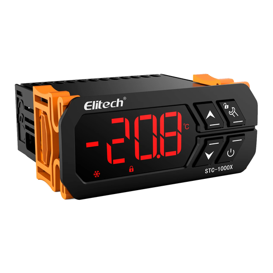
Overview
STC-1000X temperature controller features cooling and heating modes with automatic
switch, temperature unit switch between Celsius and Fahrenheit, temperature control
by set-point and differential, temperature calibration, cooling output protection delay,
sensor fault alarm and other functions. The controller reserves an interface of RS-485
communication function for further connection to an Elitech IoT module which makes
remote control available.
Specifications
Power Supply
Measurement Range
Temperature Resolution
Temperature Accuracy
Total Power Consumption
Operating Ambient Temperature
Storage Temperature
Relative Humidity
Relay Contact Output Rating
Sensor
Waterproof Grade Of Front Panel
Panel Size
Mounting Size
Product Size
Sensor Cable Length
* The details should be refer to the wiring diagram of actual device.
Operation & Display Panel
Temperature Unit Indicator
Cooling Indicator
Heating Indicator
Button Lock Indicator
Network Indicator
Button Instructions
Hold for 3 seconds: Turn ON/OFF;
Press and release: Back to previous menu
▲
Press and release: Display temperature set-point and back to normal display after 2 seconds.
Press and release: Display temperature differential set-point and back to normal display after 2
▼
seconds.
/
Hold for 3 seconds: Unlock the keyboard or enter parameter setting mode .
Quick Start
1. Unlock the keyboard
Under normal operating status, the buttons will be locked after 10 seconds of
inactivity, and the button lock indicator
than 3 seconds to unlock the buttons and
2. View parameters
Under normal operating status, press and release ▲ button to display the temperature
set-point; press and release ▼ button to display the temperature differential set-point.
The controller will be back to normal display status after 2 seconds.
3. Set parameters
Under normal operating status, press and hold
to enter parameter setting mode. The
Based on: 220V±10%, 50/60Hz;
110V±10%, 50/60Hz; 24VAC/DC; 12VAC/DC;*
-50°C~120°C/-55°F~248°F
0.1°C
±1°C (-20°C~50°C)/±2°F, ±1.5°C/±3°F (others)
< 3W
0°C~60°C
-30°C~75°C
20%~85%RH (non-condensing)
Cooling/Heating: 10A/250VAC
NTC (10K /25°C, B value = 3435K)
IP65
80 x 35 mm
71 x 29 mm
80 x 35 x 66 mm
2m (probe length included)
Up Button
Set Button
ON/OFF Button
Down Button
Setting Indicator
ON/OFF Indicator
.
will be on. Hold
/
button for more
will be off.
button for more than 3 seconds
/
indicator will be on and the first code F1
/
/
STC-1000X Microcomputer Temperature Controller User Manual
will be displayed in the panel. Press ▲ or ▼ button to scroll up or down menu items
and display the corresponding code. Press
set-point. Press ▲ or ▼ button again to increase or decrease the value and press
to back to parameter code display.
If you need to save the settings, please press and release
display status. If not, just keep the controller inactive for 10 seconds, it will be back to
temperature display status. If an error occurs during saving settings, the panel will
display Er and back to temperature display status in 3 seconds.
4. Operations
Under normal operating status, the panel displays currently measured temperature
and automatically recognizes and switches cooling and heating modes.
- If measured temperature temperature set-point + temperature differential, and
compressor delay time F3, the controller starts cooling mode and
- If measured temperature temperature set-point, the controller stops cooling and
indicator is off.
- If measured temperature temperature set-point - temperature differential, the
controller starts heating mode and
- If measured temperature temperature set-point, the controller stops heating and
indicator is off.
5. ON/OFF
Hold the power button
for more than 3 seconds to turn on/off the controller.
Menu
Code
Function
F1
Temperature Set-point
-49~109°C/-56~228°F
Temperature Differential
F2
1~10°C/33~50°F
Compressor Start Delay
F3
0~10 min
F4
Temperature Calibration
-10°C~10°C/-10~10°F
Temperature Unit
0: °C 1: °F
F5
Communication Address
F6
1~127
Fault & Alarm
When the temperature sensor is short circuit or open circuit, the controller will start
fault alarm mode and turn off all the outputs, the buzzer will beep and the panel will
display EE. Press any button to mute the buzzer.
The controller will return to normal operating mode after the fault is removed.
Safety Precautions
Important!
1. Distinguish the sensor lead, power cord and output relay interface. Do not connect
wrong or overload the relay.
2. Cut off power supply before wiring.
Warning!
Do not use the controller in water or too humid environment, or environments at high
temperature, with strong electromagnetic interference or strong corrosion.
Wiring Diagram
Power
Sensor
Caution!
1. The power voltage must be in accordance with the voltage labeled on the controller.
Please ensure the stability of power voltage.
2. Separate as much as possible the sensor lead from power cables to avoid possible
electromagnetic disturbance.
button to display the current parameter
/
/
button and back to normal
indicator is on.
indicator is on.
Setting Range
Default
Remark
10°C/50°F
3°C/37°F
3
0°C/0°F
0
1
Reserved
L
Heating
Cooling
N
Advertisement

Related Manuals for Elitech STC-1000X


Summary of Contents for Elitech STC-1000X
- Page 1 If you need to save the settings, please press and release button and back to normal communication function for further connection to an Elitech IoT module which makes display status. If not, just keep the controller inactive for 10 seconds, it will be back to remote control available.
- Page 2 STC-1000X 微电脑温度控制器说明书 3、设定参数方法:控制器正常工作时,按住 键持续3秒以上进入修改参数 主要功能 模式, 指示灯亮,数码管显示第一个菜单项的代码“F1” 。按“▲”键或“▼” 制冷制热自动转换模式,新增℃/℉转换功能,按照温度设定值和回差进行温度 键可上翻或下翻菜单项并显示菜单项的代码,按 键显示当前菜单的参数 控制;温度校正;制冷控制输出保护延时,传感器报警等功能;预留485通讯功 设定值,再按“▲”键或“▼”键可上调或下调并显示当前菜单的参数设定值 能,搭配精创联网模块实现远程控制。 ,设置完毕后,按 返回参数代码,按下并松开 键则保存参数修改 并返回正常温度显示状态。10秒内如无任何按键操作则不保存,本次参数修改 并返回正常显示状态。保存参数时如果出现错误则显示“Er”,3秒后返回正常显示 状态。 功能及技术参数 4、操作运行说明:控制器正常工作时,数码管显示当前温度测量值,并进行 制冷制热工作模式自动识别转换: 根据型号有: 220V±10%, 50/60Hz; 电源 当测量温度≥温度设定值+温差设定值且压机延时≥F3时,启动制冷, 指示灯亮 110V±10%, 50/60Hz; 24VAC/DC; 12VAC/DC; * ; 测量范围 -50°C~120°C/-55°F~248°F 当测量温度≤温度设定值,停止制冷, 指示灯灭; 当测量温度≤温度设定值-温差设定值时,启动加热,...
Need help?
Do you have a question about the STC-1000X and is the answer not in the manual?
Questions and answers