Advertisement
E L E C T R O N I C C I R C U I T S
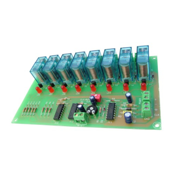
SEQUENTIAL COMMAND 8 OUTPUTS
The I-55 module is a sequential command with 8 relay outputs. With each impulse, relays will be connected one after
one, and disconnecting the previous one.
The sequence could be produce by external impulses or thanks to an internal oscillator.
The oscillator is adjusted with a potentiometer inserted in the PCB. It includes reset output, protection against polarity
inversion, indicator output led and terminals to connect it.
Do not forget to read all the information sheet in order to obtain a perfect operating of the module.
TECHNICAL CHARACTERISTICS.
Voltage ................................................................................................... 12 V. D.C.
Minimum Consumption ......................................................................... 50 mA.
Maximum Consumption ........................................................................ 60 mA.
External Clock - input maxi. Frequency .................................................. 25 Hz.
Internal Clock - Mini. Connection time by relay ..................................... 0,3 Sec.
Internal Clock - Maxi. Connection time by relay .................................... 10 Sec.
Maximum Output Load By Relay ........................................................... 5 A.
Protection Against Polarity Inversion ...................................................... Yes
Sizes ....................................................................................................... 155 x 102 x 30 mm.
OPERATING.
POWER SUPPLY.
The I-203 circuit had to be supplied by a 12 VDC power supply.
Then, we recommended you the FE-2 power supply which has been developed to perfectly answer to the circuit needs
or a 12 V batteries for mobile applications. Install a fuse and a switch as it is indicated in the drawing. Both are
obligatory to guarantee a correct protection of the module as well as for your own safety as it is required by the "CE"
marking.
Connect the positive of the power supply to the positive terminal indicated in the wiring map, then connect also the
negative of the power supply to the negative terminal indicated in the circuit.
correctly done.
OPERATING.
See the general wiring map. The module has a switch indicated as INT-1. Thanks to this switch you could
select between automatic operating (controlled by the internal oscillator) and manual operating which be externally
inserted.
Regarding manual operating.
Nº2 in OFF position. Do not place permanently both contact in the same position to avoid to damage the module. See
the drawing.
Connect a push button to the terminal indicated as impulses input (See General wiring map). If you have to connect a
clock signal from an other apparatus, you have to respect their polarity and verify that it is a 12 VDC signal.
When the push button is installed, after each pressure relay will be activated one after one, and disconnecting the
previous one.
Regarding automatic operating.
contact Nº2 in ON position. Do not place permanently both contact in the same position to avoid to damage the
module. See the drawing.
Adjust the speed using the potentiometer inserted in the PCB to adjust the frequency. After each pressure relay will be
activated one after one, and disconnecting the previous one.
ON
RESET
. See the general wiring map. Connect a push button to the terminal indicated as "Reset". Each time you press
this push button and independently of the activated relay, the module will come back at the beginning of the sequence
(to the first relay) until you stop to press the "reset" push button.
you have to place (in the switch INT-1) the contact Nº1 in ON position and the contact
you have to place (in the switch INT-1) the contact Nº1 in OFF position and the
Manual Operating
External Clock
Verify
that the assembly has been
ON
Automatic Operating
Internal Clock
Advertisement
Table of Contents

Related Manuals for CEBEK I-55


Summary of Contents for CEBEK I-55
- Page 1 E L E C T R O N I C C I R C U I T S SEQUENTIAL COMMAND 8 OUTPUTS The I-55 module is a sequential command with 8 relay outputs. With each impulse, relays will be connected one after one, and disconnecting the previous one.
- Page 2 OUTPUT. CONNECTION OF THE LOAD. OUTPUT. CONNECTION OF THE LOAD. The output Module (I-55) is controlled by a relay, allowing any load until 5 A. as maximum consumption. The relay has 3 output terminals the normally open at quiescent (NA), the normally closed at quiescent (NC) and the common.
Need help?
Do you have a question about the I-55 and is the answer not in the manual?
Questions and answers