Table of Contents
Advertisement
Quick Links
Advertisement
Table of Contents

Related Manuals for Bindicator VRF-1000 Series

Summary of Contents for Bindicator VRF-1000 Series
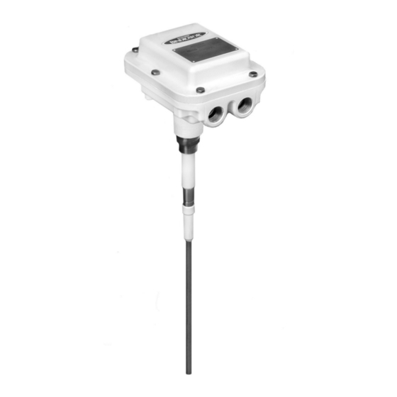
- Page 1 VRF-1000 Series Integral Electronics with Opti-Sense™ Installation, Operation, and Maintenance Manual CAUTION It is essential that all instructions in this manual be followed precisely to ensure proper operation of the equipment. VRF180000 Revision G September 2010...
- Page 2 The VRF-1000 sensor must only be installed and operated as described in this instruction manual. Note that other actions can cause damage for which Bindicator does not take responsibility. If the model is ®...
-
Page 3: Table Of Contents
TABLE OF CONTENTS CHAPTER 1. PRODUCT DESCRIPTION ....................1 Function ..............................1 Applications ..............................1 Model Code Identification .......................... 2 Technical Specifications/Approvals ......................3 Dimensions ..............................3 CHAPTER 2. HANDLING AND STORAGE ....................4 Inspection and Handling ..........................4 Storage ............................... 4 CHAPTER 3. -
Page 4: Chapter 1. Product Description
Material coming in contact with the unit’s probe causes its output relay to change state, thereby indicating to the user the presence of material. Operation of the VRF-1000 is based upon the Bindicator Opti-Sense™ technology using Variable Radio ®... -
Page 5: Model Code Identification
MODEL CODE IDENTIFICATION Note 1: For 3A Sanitary Certification, add “3A”at the end of the model code. Assembly S must be used and either Probe Type 2 (Food Grade Polysulfone) or Probe Type 4 (Stub Polysulfone) must be used. Note 2: Thickness of probe must be specified: 3/8 in., 1/2 in., 5/8 in., or 3/4 in. wall thickness. Note 1: Maximum length is 45 ft. -
Page 6: Technical Specifications/Approvals
TECHNICAL SPECIFICATIONS/APPROVALS ELECTRONICS Line Voltage AC Models 85VAC to 265VAC; DC Models 10VDC to 36VDC Power Consumption 5.5 watts maximum Output Relay 2 form C (DPDT), 6A at 240VAC, 6A at 30VDC, minimum load 12V/100mA Temperature Range -40° F to +158° F (-40° C to +70° C) Sensitivity Settings See Chapter 5 Selectable Time Delay... -
Page 7: Chapter 2. Handling And Storage
If the unit is received damaged, DO NOT dispose of the carton or packing materials. Notify the shipping carrier immediately. If any problems arise, please contact Bindicator at (800) 778.9242 or (864) 574.8060. -
Page 8: Chapter 3. Mechanical Installation
CHAPTER 3. MECHANICAL INSTALLATION GUIDELINES The probe can be mounted on the side of the vessel horizontally, or on the top of the vessel vertically. The probe should be located out of the direct flow of material into the vessel. MOUNTING Consult the appropriate dimensional drawing in the Appendix for mounting information related to the model ordered. -
Page 9: Chapter 4. Electrical Installation
CHAPTER 4. ELECTRICAL INSTALLATION GUIDELINES The VRF™ unit is a line powered point level switch with a DPDT isolated relay contact output. Wiring will consist of: Grounding Input supply line power Output relay contacts for signal/control CONDUIT-CABLE CONNECTION Two threaded 0.75 in. NPT female conduit openings are provided in the housing for input and output wiring. - Page 10 The output relay contacts are labeled in the un-powered alarm state. The relay is energized when the ® VRF-1000 is not alarmed. This status may be opposite that of other Bindicator brand units. If the VRF-1000 is replacing an older Model RF-8000 or RF-9000 Series unit, connections will need to be opposite.
-
Page 11: Chapter 5. Set-Up And Calibration
CHAPTER 5. SET-UP AND CALIBRATION OPERATION The VRF™ unit will begin operating when powered up. The sensitivity, fail-safe, and time delay settings can be made without power applied. Recalibration will require that the unit be powered. Changes to the sensitivity, fail-safe, and time delay do not require a recalibration. SETTINGS AND ADJUSTMENTS FAIL-SAFE SELECTION The VRF™... -
Page 12: Enable Automatic Calibration Feature
ENABLE AUTOMATIC CALIBRATION FEATURE The VRF-1000 is shipped form the manufacturing facility with the EZ-CAL™ II feature disabled (OFF). If automatic calibration/recalibration is desired, set the SW1 DIP switch position 6 to ON. When enabled, the unit will automatically recalibrate whenever it senses a lower capacitance than the previously calibrated point. -
Page 13: Chapter 6. Start-Up And Operation
CHAPTER 6. START-UP AND OPERATION The VRF-1000 will begin operating when powered up. Once properly installed in the application, it should be calibrated when material is below the probe. If the automatic calibration feature is turned ON, the unit will self calibrate to the current conditions, assuming that there is no material on the probe. If there is material present, and the automatic calibration is ON, the unit will automatically recalibrate when material level drops below the probe. -
Page 14: Chapter 7. Maintenance And Spare Parts List
CHAPTER 7. MAINTENANCE AND SPARE PARTS LIST If it should become necessary to replace any parts on the VRF-1000 Series unit, please contact Bindicator at (800) 778.9242 or (864) 574.8060. Please note the model number and date code from the ®... -
Page 15: Chapter 8. Troubleshooting
• Recalibrate the unit as described in Chapter 6. • Check for excessive material build-up or physical damage to the probe. ® If further assistance is needed, please contact Bindicator Customer Care at (800) 778.9242 or (864) 574.8060. -
Page 16: Appendix
APPENDIX DRAWING NUMBER DRAWING DESCRIPTION VRF185001 Dimensional Drawing for GP VRF-1000 and VRF-2000 VRF185002 Dimensional Drawing for VRF-1000 and VRF-2000 GP Cable Probe VRF185003 Dimensional Drawing for Dome Flush Probe VRF-1000 and VRF-2000 VRF185004 Outline Drawing VRF Extended, G/P Type “B” Mounting VRF185005 Outline Drawing VRF Extended, G/P Type “C”... - Page 28 150 Venture Boulevard © 2010 Venture Measurement. Spartanburg, SC 29306 All rights reserved. (800) 778.9242 [Toll Free] All data subject to change. (864) 574.8060 [Phone] (864) 574.8063 [Fax] VRF180000 www.bindicator.com Revision G September 2010 sales@bindicator.com...
Need help?
Do you have a question about the VRF-1000 Series and is the answer not in the manual?
Questions and answers