Table of Contents
Advertisement
Quick Links
Advertisement
Table of Contents

Related Manuals for Embention MC24


Summary of Contents for Embention MC24
- Page 1 MC24 Embention Dec 14, 2022...
-
Page 3: Table Of Contents
CONTENTS 1 Introduction 2 Quick Start Warnings ..........Requirements . - Page 5 MC24 CONTENTS...
- Page 6 MC24 CONTENTS...
-
Page 7: Introduction
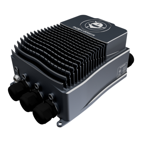
CHAPTER INTRODUCTION Veronte MC24 speed controller is capable of driving any type of 3-phase PMSM motor. It can be used with a wide variety of UAVs or eVTOL vehicles and also in automotive applications (Bikes, Karts, Cars).The MC24 uses FOC algorithm for motor control together with MOSFET technology. - Page 8 MC24 MC24 rear view Chapter 1. Introduction...
-
Page 9: Quick Start
Careful! The system slowly discharges the voltage on the input terminals when the battery is Warning: disconnected. Capacitors may remain charged unless enough time has passed. 2.2 Requirements To dissipate the heat from the MC24 properly, there is a need to provide 16m/s of air speed against the heatsink. - Page 10 MC24 Airflow dissipation Chapter 2. Quick Start...
-
Page 11: Technical
CHAPTER THREE TECHNICAL 3.1 Electrical Specifications Table 1: Electrical Characteristics Type Specification Voltage 60-120DC Cont. Current (rms at battery input) 5 - 200A Peak Current (<5s) 400A Maximum speed (1 pole) 600000 ERPM PWM frequency 10 kHz Weigth 2430g This is the main power input for the secondary part of the driver. It must be powered with a voltage of 8 to 20V. The consumption of this pin also depends on the loads connected to 5V pin. - Page 12 NTC/PTC sensor. ERROR_SIGNAL This signal indicates if there is an error within the MC24. A positive voltage of 3.3V means that there is no problem. SIN/COS_SIGNAL These signals are those dedicated to the SIN / COS type analog sensor. There is a 100K ohms resistor to act as divider so the maximum voltage on the pin does not exceed 250mV.
- Page 13 2.9 to 4.5V Motor This tab sets all the physical parameters of the motor that will be used with Veronte MC24. These are: 1. Stator internal resistance: This is the resistance that is usually specified in datasheets. Expressed in Ohms.
-
Page 14: Mechanical Specifications
• Serial RS-485 • USB Any of the serial interfaces can be used to configure the internal variables of the MC24. The ESC includes an internal SD memory which is used to record operating logs. The variables to store can be selected through the corresponding interface. - Page 15 MC24 Dimensions 3.2. Mechanical Specifications...
-
Page 16: System Diagram
MC24 3.3 System Diagram 3.4 FOC (Field Oriented Control) Background In order to achieve better dynamic performance, a more complex control scheme needs to be applied, to control the PM motor. With the mathematical processing power offered by the microcontrollers, we can implement advanced control strategies, which use mathematical transformations in order to decouple the torque generation and the magnetization functions in PM motors. -
Page 17: Interfaces
MC24 As it can be seen, there some key pieces in this algorithm: 1. Park/Clark transform: These output a two co-ordinate time invariant system and a outputs a two co-ordinate time variant system respectively. As mentioned before, this is part of the process of getting two scalar values from a three phase time dependent system. - Page 18 MC24 Name Commercial reference Embention reference Sensor cable FGG.1K.316.CLAC65Z P005591 Phase C Wurth M8 5580870 P005590 Phase B Phase A In negative In positive User cable FGG.3K.324.CLAC90 P005704 Chapter 3. Technical...
-
Page 19: Hardware Installation
CHAPTER FOUR HARDWARE INSTALLATION The MC24 system has the following positions of mounting holes: Mounting Holes... -
Page 20: Pinout
MC24 4.1 Pinout The user connector pinout is shown in the following figures and table: Point of view Pin numbers of user connector Chapter 4. Hardware Installation... - Page 21 MC24 Table 1: User Connector Signal Type Comment ERROR_SIGNAL Digital Status Signal High: OK, Low: OPTO_PWM Optocoupled Digital Input Digital Supply 8-20V Digital Ground CANA_P CAN Communications CANA_N CAN Communications CANB_N CAN Communications Digital Ground RS485_OUT_P RS-485 Communication RS485_OUT_N RS-485 Communication...
- Page 22 MC24 Point of view Pin numbers of sensor connector Table 2: Sensors Connector Signal Type Comment HALL_1 Hall Sensor 1 Input No Connect No Connect No Connect COS_SIGNAL Cosine Input SIN/COS Encoder SIN_SIGNAL Sine Input SIN/COS Encoder ISO_GND Isolated Ground...
-
Page 23: Esc-Motor Wiring
MC24 4.2 ESC-Motor Wiring The polarity and connection is indicated in the following image. The section of the cables must be dimensioned according to input/output max power Note: The polarity connection of the input must be respected, otherwise a short circuit may occour. Connection of the phases can be done freely, however, it will affect the direction of rotation of the motor. - Page 24 MC24 Chapter 4. Hardware Installation...
-
Page 25: Software Installation
CHAPTER FIVE SOFTWARE INSTALLATION To properly configure and connect to a MC24 unit, read the Software manual. - Page 26 MC24 Chapter 5. Software Installation...
-
Page 27: Maintenance
CHAPTER MAINTENANCE Apart from cleaning, no extra maintenance is required to guarantee the correct operation of the Veronte MC24. In order to clean Veronte MC24 properly follow the next recommendations. • Turn off the device before cleaning. • Use a clean, soft, damp cloth to clean the unit. - Page 28 MC24 Chapter 6. Maintenance...
-
Page 29: Acronyms And Definitions
CHAPTER SEVEN ACRONYMS AND DEFINITIONS Pulse Width Modulated signal PMSM Permnent Magnet Synchronous Motor Unmaned Aerial Vehicle VTOL Vertical Take Off and Landing Field Oriented Control MOSFET Metal Oxide Semiconductor Field Effect Transistor Controller Area Network RS-232 Recommended Standard 232 RS-485 Recommended Standard 485 Root Mean Squared... - Page 30 MC24 Chapter 7. Acronyms and Definitions...
-
Page 31: Contact Data
CHAPTER EIGHT CONTACT DATA You can contact Embention in any moment if you need further help and support. Embention contact data is as follows: Email: support@embention.com Telephone: (+34) 965 421 115 Address: Polígono Industrial Las Atalayas, C/ Chelín, Nº 16, CP 03114, Alicante (España).
Need help?
Do you have a question about the MC24 and is the answer not in the manual?
Questions and answers