Table of Contents
Advertisement
Quick Links
Advertisement
Table of Contents

Related Manuals for Amersham Biosciences AKTA design P-960


Summary of Contents for Amersham Biosciences AKTA design P-960
- Page 1 Pump P-960 User Manual 18-1172-73...
- Page 3 Unless otherwise agreed in writing, all goods and services are sold subject to the terms and conditions of understand the safe use of Pump P-960. sale of the company within the Amersham Biosciences group which supplies them. A copy of these terms and WARNING! conditions is available on request.
-
Page 5: Table Of Contents
Contents 1 Introduction General ..................7 Safety ..................8 2 Installation Unpacking .................. 9 General precautions ..............9 Installing the pump ..............9 Connecting UniNet-2 cables ............. 10 Connecting the tubing ............... 11 Connecting the flow restrictor ............ 12 Initializing Pump P-960 in UNICORN ........13 Removing air from the sample flow path ........ - Page 6 Short instructions on back page About this manual This manual comprises two parts; a practical part (sections 1–5) and a reference part (section 6). Sections 1–5 contain the necessary information for installing, operating and maintaining the instrument. Pump P-960 User Manual 18-1172-73 Edition AA...
-
Page 7: Introduction
A pressure sensor connected to the pump outlet. • Interface for connecting an air sensor directly to the pump. Pump P-960 works with a wide range of columns and media supplied by Amersham Biosciences. ™ The pump is controlled from a PC running UNICORN control system, version 4.12 or later. -
Page 8: Safety
Introduction 1.2 Safety • The unit is designed for indoor use only. • Do not use in a dusty atmosphere or close to spraying water. • Do not block the outlet of the unit. WARNING! HAZARDOUS CHEMICALS. When using hazardous chemicals, all suitable measures, such as wearing protective glasses, must be taken. -
Page 9: Installation
Installation 2 Installation 2.1 Unpacking Unpack the unit and check the items against the supplied packing list. Inspect the items for obvious damage that may have occurred during transportation. Keep all packing materials if onward transport of the unit is expected. CAUTION! Read the following information carefully to ensure that the unit is installed correctly. -
Page 10: Connecting Uninet-2 Cables
Installation 2.4 Connecting UniNet-2 cables Pump P-960 is controlled from a PC running UNICORN version 4.12 or higher via a UniNet-2 cable. Power is also supplied through this cable. The UniNet-2 chain connects, in series, Pump P-900/Pump P-920 with Pump P-960 and other modules. In ÄKTAdesign chromatography systems that include Pump P-960 as a standard component, the UniNet-2 cables are installed at delivery. -
Page 11: Connecting The Tubing
Installation 2.5 Connecting the tubing WARNING! HAZARDOUS CHEMICALS. Incorrectly fitted tubing might loosen, causing a jet of liquid to spray out. This is especially dangerous if hazardous chemicals are being used. Connect the tubing by first inserting the tubing fully, then tightening the connector fingertight. -
Page 12: Connecting The Flow Restrictor
Installation 2.6 Connecting the flow restrictor If the sample vessel is placed at a higher level than the end of the sample waste tubing, sample might flow to waste. Flow restrictor FR-902 supplied is used in the sample flow path to eliminate this siphon effect by creating a back-pressure of 0.2 MPa. -
Page 13: Initializing Pump P-960 In Unicorn
Installation 2.7 Initializing Pump P-960 in UNICORN Make sure that the correct strategy is installed. , select UNICORN Main menu Admininstration:System Setup Select the system used and click Edit Click Component Select and click Sample pump P-960 Click again and then to complete the initialization. -
Page 14: Operation
Operation Operation 3.1 General Pump P-960 switches on automatically when the chromatography system is switched on. Pump P-960 is controlled from a PC running UNICORN version 4.12 or higher. It cannot be used as a stand-alone instrument. Control of the pump can be achieved automatically from a method, or manually via the functions available in UNICORN. - Page 15 Operation Purge the pump before use as described in section 5.2 Removing trapped air bubbles from the sample pump or in ÄKTAdesign Optional Configurations User Manual. Set the pressure limit as described in section 3.4 Setting the pressure limit. If the pressure limit is exceeded, the pump is paused. Note: When applying the sample directly onto the column, some columns generate a back-pressure above 2.0 MPa (the upper pressure limit of Pump P-960) at their recommended flow...
-
Page 16: Setting The Pressure Limit
Alternatively, follow the instruction for your configuration in the ÄKTAdesign Optional Configurations User Manual. If the flow rate remains out of specification, contact the local Amersham Biosciences service representative. 3.5.1 Calibrating the pressure offset To calibrate the pressure offset: Expose the pressure sensor to atmospheric pressure only. -
Page 17: Filling The Sample Inlet Tubings
Operation 3.6 Filling the sample inlet tubings We recommend using a purge tubing for filling the sample inlet tubings and the sample pump. When the tubings are empty or the pump is dry, the purge tubing must be used. The procedure for using the purge tubing is described in section 5.2.2 Removing air using a purge tubing. -
Page 18: Ending The Run And Storage
Operation 3.8 Ending the run and storage If no further runs are planned, Pump P-960 should be flushed immediately with at least 50 ml of pure, distilled water. If aqueous buffers have been in use, this is particularly important to prevent salt precipitation. -
Page 19: Maintenance
Maintenance 4 Maintenance The flow path components in Pump P-960 have a limited lifetime, which depends on the flow rate, pressure and eluents used. WARNING! Always disconnect the power supply before attempting to replace any item on the unit. WARNING! HAZARDOUS CHEMICALS. Incorrectly fitted tubing might loosen, causing a jet of liquid to spray out. -
Page 20: General Care
Maintenance 4.2 General care Inspect the pump daily for liquid leaks. If you suspect that air bubbles are trapped in the sample flow path, go through the air removal procedure for your configuration described in section 5.2 Removing trapped air bubbles from the sample pump, or in ÄKTAdesign Optional Configurations User Manual. -
Page 21: Removing And Installing The Connection Part
Maintenance 4.4 Removing and installing the connection part The connection part should be removed to make it easier to remove the check valves and the O-rings. 4.4.1 Required tools • Hex wrench, 4 mm 4.4.2 Removing the connection part Before disassembling the pump, move the input liquid bottle below the level of the pump to prevent siphoning. -
Page 22: Replacing The Connection Part O-Rings
Maintenance 4.5 Replacing the connection part O-rings Liquid appearing between the connection part and the pump assembly, irregular flow, or unstable pressure might indicate that an O-ring in the connection part is damaged. 4.5.1 Required spare parts and tools • O-ring kit (see Ordering information for code no.) 4.5.2 Replacing an O-ring... - Page 23 Maintenance 4.6.2 Removing the check valves If the condition of the check valve is not improved by cleaning, remove it as follows: Remove the connection part according to section 4.4.2 Removing the connection part. The check valves in the Check valve connection part are locked in position with banjo fittings.
- Page 24 Maintenance 4.6.5 Installing the check valves Note: An inlet check valve can be installed incorrectly in an outlet check valve position, and vice versa. Make sure that the check valves are installed in their correct positions. If cleaning of the check valve as decribed in section 4.6.3 Cleaning the check valves does not correct the fault, replace the check valve with a new one.
-
Page 25: Troubleshooting
Troubleshooting 5 Troubleshooting WARNING! LETHAL VOLTAGE. Always disconnect the power supply before attempting to replace any item on the unit. WARNING! HAZARDOUS CHEMICALS. Incorrectly fitted tubing might loosen, causing a jet of liquid to spray out. This is especially dangerous if hazardous chemicals are being used. Connect the tubing by first inserting the tubing fully, then tightening the connector fingertight. - Page 26 Troubleshooting Error symptom Possible cause Corrective action Measured volume too low Air bubbles are trapped in the Purge the pump according to pump section 5.2 Cavitation might occur due to See the ÄKTAdesign Optional too high flow rate for the Configurations User Manual sample application technique for the recommended flow...
- Page 27 Troubleshooting Error symptom Possible cause Corrective action High pressure limit exceeded The pump inlet or outlet Check the pump tubing. tubing is pinched or damaged Replace if necessary. A check valve is clogged or Remove the check valve damaged according to section 4.6.2. Clean the check valve in an ultrasonic bath.
-
Page 28: Removing Trapped Air Bubbles From The Sample Pump
Troubleshooting 5.2 Removing trapped air bubbles from the sample pump During routine operation, the presence of air bubbles in the pump heads is seen as an erratic flow, a flow that is lower than expected, or an irregular pressure recording. If the sample pump is completely dry, it might fail pumping liquid. - Page 29 Troubleshooting 5.2.2 Removing air using a purge tubing If there is plenty of air in the sample inlet tubings or if the sample pump is dry, use a purge tubing to fill the tubings and the pump. Procedure for system including sample valve V5 This procedure describes how to first fill the sample inlet tubings and then the buffer inlet tubing.
- Page 30 Troubleshooting Switch sample valve V5 to the next sample inlet tubing to be filled. Note: To empty the syringe, switch valve V5 before removing the syringe to prevent sample from flowing back to the vessel. Repeat step 6 and 7 for the remaining sample inlet tubings. To fill the buffer inlet tubing in port 8: Set the sample valve V5 to port 8.
-
Page 31: Reference Information
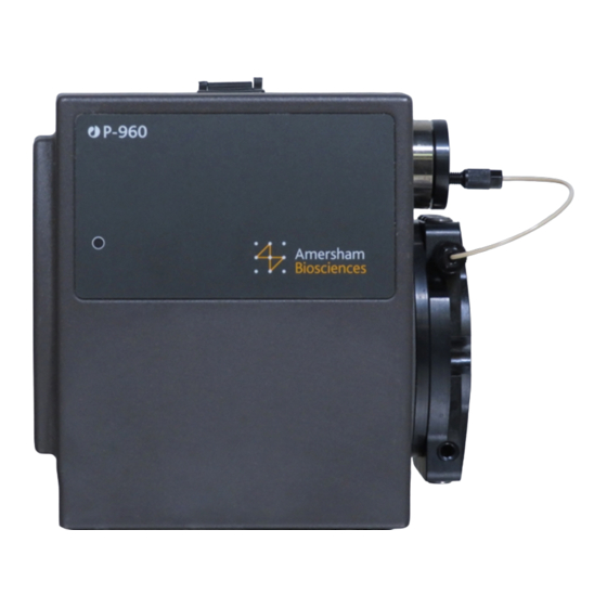
Reference information 6 Reference information 6.1 Description Pump P-960 is a single-channel laboratory pump for use as a sample pump in ÄKTAdesign liquid chromatography systems. Liquid in an external vessel is drawn into the pump by three plunger pumps. They are actuated in a sequential order by a stepper motor. -
Page 32: Liquid Delivery
Reference information 6.3 Liquid delivery Pump P-960 has one inlet port and one outlet port. In the connection part, the inlet flow path as well as the outlet flow path are split into three separate flow paths – one to each plunger pump chamber. All six flow paths are equipped with non-return check valves. -
Page 33: Technical Specifications
Reference information 6.4 Technical specifications 6.4.1 Operating data Flow rate range 0.1–50 ml/min in steps of 0.1 ml/min Pressure range 0–2.0 MPa (20 bar, 290 psi) ≤ Pressure pulsation ±10% of mean value in entire operating range Flow rate accuracy -5 –... - Page 34 Reference information Chemical resistance The wetted parts are resistant to the chemicals listed below (synergistic effects have not been taken into account; room temperature and limited over- pressure is assumed). Unless otherwise stated, all concentrations are 100%: Acetic acid, 0.1 M Acetone, 1% Aqueous buffers, pH 2–12 Decon 90, 10% (for washing only)
-
Page 35: Ordering Information
Reference information 6.5 Ordering information Item Quant./pack Code no. Pump P-960 kit, including Pump P-960, 18-6727-00 holders for ÄKTA systems, UniNet cable, flow restrictor, purge kit, union, connectors, and tubing Sample valve kit, including valve PV-908, 18-1175-86 UniNet cable, Sample holder SH-900, unions, connectors, and tubing Air sensor Air-912N kit, including Air 18-1175-84... - Page 36 Reference information Item Quant./pack Code no. Union 1/16" female/M6 male, PEEK 18-1112-57 (from finger-tight connector 1/16" to P-960 inlet port) Union 5/16" female/M6 male, PEEK 18-1127-76 (from o.d. 1/8" and 3/16" tubing connector to P-960 inlet port) Stop plug, 5/16", PEEK 18-1112-50 Stop plug, 1/16", PEEK 18-1112-52...
- Page 37 Reference information Pump P-960 User Manual 18-1172-73 Edition AA...
- Page 38 Reference information Pump P-960 User Manual 18-1172-73 Edition AA...
- Page 40 Short instructions The following short instructions are intended as a guide for users who are fully familiar with the safety precautions and operating instructions described in this manual. The instructions assume that the unit is installed according to the installation instructions. Pump P-960 is controlled from UNICORN.
Need help?
Do you have a question about the AKTA design P-960 and is the answer not in the manual?
Questions and answers