Table of Contents
Advertisement
Quick Links
FEATURES
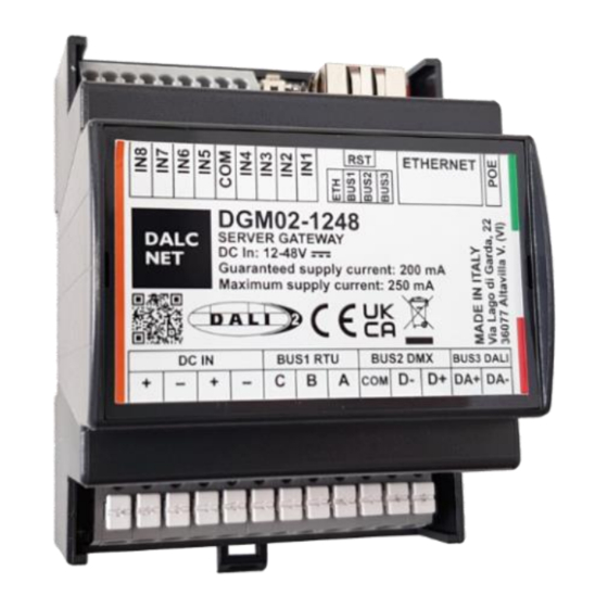
SERVER GATEWAY
POWER INPUT: 12-24-48 Vdc
ETHERNET BUS: 10/100Mbit
MODBUS BUS: range baud rate 9600 – 250000
DMX BUS: 1 universe DMX512
DALI BUS: 1 DALI line – integrated DALI bus power supply
⇢ For the always updated manual, consult our website:
TECHNICAL SPECIFICATIONS
Supply voltage
Input current
Nominal Power
1
PoE
1
ETHERNET
MODBUS RTU
DMX
DALI
Storage temperature
Ambient temperature
Protection grade
Casing material
Packaging units (pieces/units)
Mechanical dimensions
Package dimensions
Weight
1
Values may differ by ± 5%
2
Only with BUS 3 config in NOT USE
DALCNET S.r.l.
36077 Altavilla Vicentina (VI) – Italy
Via Lago di Garda, 22
DGM02
Device Manual
@12V
160 mA (1.92W)
@24V
80 mA (1.92W)
@48V
50 mA (2.40W)
min
2
@46.5V
40 mA (1.9W)
Integrated power supply: 200mA / 16Vdc
www.dalcnet.com
or the QR on the product
DGM02-1248
12 / 24 / 48 Vdc
550mA max
typ
100 mA (4.65W)
10 / 100 Mbit baseT FULL DUPLEX AUTO NEGOTIATION
RS-485, BAUD RATE da 9600 a 250000
512 CHANNELS
64 ADDRESS
Min: -40°C ÷ Max +60°C
Min: -40°C ÷ Max +60°C
Plastic
72 x 92 x 62 mm
85 x 124 x 71 mm
100g
max
550 mA (6.60W)
260 mA (6.24W)
150 mA (7.20W)
typ
170 mA (7.9W)
Guaranteed bus current = 200mA
Max bus current = 250mA
IP10
1pz
Tel. +39 0444 1836680
www.dalcnet.com
Rev. 06/12/2022 - Pag. 1/32
Made in Italy
max
–
info@dalcnet.com
Advertisement
Table of Contents

Subscribe to Our Youtube Channel
Related Manuals for DALCNET DGM02


Summary of Contents for DALCNET DGM02
- Page 1 DGM02 Device Manual Made in Italy FEATURES SERVER GATEWAY POWER INPUT: 12-24-48 Vdc ETHERNET BUS: 10/100Mbit MODBUS BUS: range baud rate 9600 – 250000 DMX BUS: 1 universe DMX512 DALI BUS: 1 DALI line – integrated DALI bus power supply ⇢...
- Page 2 Il DGM02 set commands for control gear DT4, compatible with the standard IEC 62386-205 Il DGM02 set commands for control gear DT6, compatible with the standard IEC 62386-207 Il DGM02 set commands for control gear DT8, compatible with the standard IEC 62386-208 (colour type Tc, colour type RGBWAF) DALCNET S.r.l.
- Page 3 DGM02 Device Manual Made in Italy WIRING DIAGRAM RESET WIRING 2 BUTTON WIRING 1 WIRING 3 WIRING 1 WIRING 2 WIRING 3 DMX wired with XLR connector PINOUT CONNECTORS PIN OUT PLUG-IN CONNECTORS Vin+ Vin- DC IN Vin+ RJ45/A (RJ45/B crossed)
- Page 4 DGM02 Device Manual Made in Italy ONBOARD LED FUNCTION BLINK Wired and LED1 Ethernet communicating via Wired with ethernet Not wired (First from left) ethernet Connected with no Connected with LED2 BUS1(RTU/ DMX) communication (only BUS1 not enabled communication RTU)
- Page 5 DGM02 Device Manual Made in Italy TECHNICAL NOTE INSTALLATION: • CAUTION: The product may only be connected and installed by a qualified electrician. All applicable regulations, legislation, and building codes must be observed. Incorrect installation of the product can cause irreparable damage to the product and the connected LEDs.
-
Page 6: Table Of Contents
DGM02 Device Manual Made in Italy SUMMARY SERVER GATEWAY SERVER GATEWAY ....................................7 HOME PAGE ......................................8 Device info ......................................8 web side led info ....................................8 WEB INTERFACE ......................................9 SECTION: CHANNEL ....................................10 SECTION: BUS CONFIGURATION ................................11 Bus 1 ....................................... 11 Bus 2 ....................................... 11 Bus 3 ....................................... -
Page 7: Server Gateway
SERVER GATEWAY The DGM02 device converts information between multiple protocols in real time. It is able to acquire information from the ethernet network and from one or more buses (configured as reception buses), transmitting and converting them to the ethernet network and the buses configured as transmission. -
Page 8: Home Page
DGM02 Device Manual Made in Italy HOME PAGE EVICE INFO In the “HOME” screen it is possible to view the information of the device in use such as: Dashboard version, Firmware version, TCP / IP stack version. On this page you can select the following sections: ... -
Page 9: Web Interface
(not visible if in DALI CONFIG mode); Bus Configuration: in this page it is possible to configure the settings for each single physical bus on the DGM02; Dali global settings: in this page it is possible to configure the settings for the DALI bus (modifiable only if in DALI CONFIG mode);... -
Page 10: Section: Channel
Made in Italy SECTION: CHANNEL The DGM02 has a WebApp for the supervision and regulation of all the channels available in the various DALI, DMX, MODBUS protocols, which can be used from any device equipped with a compatible browser. By default, a window for managing 16 channels is displayed. Using the "NUMBER OF SLIDERS" icon you can choose how many channels to see in a single screen (no more than 200) and, thanks to the "DISPLAY MODE"... -
Page 11: Section: Bus Configuration
DGM02 Device Manual Made in Italy SECTION: BUS CONFIGURATION BUS 1 is related to the first RS485 port. You can set this port in the following configurations: Not Set RS485 MODBUS RTU master RS485 MODBUS RTU slave ... -
Page 12: Bus 3
DGM02 Device Manual Made in Italy Bus 3 is related to the third BUS port of the product. The DALI protocols. You can set this port in the following configurations: Not Set DALI controller DALI config In this menu it is possible to assign the "OFFSET" and "CHANNELS RANGE" of the 64 DALI nodes to the BUS 3 channels. -
Page 13: Section: Dali Global Settings - Bus 3
DGM02 Device Manual Made in Italy SECTION: DALI GLOBAL SETTINGS – BUS 3 Only in Dali config mode it is possible to send and modify the commands of the DALI global settings pop-up menu which are: “TRANSMIT AS”: “Address”: send address commands “Group”: send group commands... -
Page 14: Settings: Dali Config - Bus 3
DGM02 Device Manual Made in Italy SETTINGS: DALI CONFIG – BUS 3 NOTE: before proceeding with the addressing and configuration of the DALI devices, it is necessary to set BUS 3 in DALI Config mode. DDRESSING By clicking on "DALI config" from the pop-up menu, we enter the DALI device addressing interface. -
Page 15: Address Change From The Devices Already Addressed
DGM02 Device Manual Made in Italy DDRESS CHANGE FROM THE DEVICES ALREADY ADDRESSED To change the address of the single DALI node, previously addressed, it is necessary to enter the new node value (eg from 0 to 63) to the right of the flashing button of the node itself and click the "APPLY" button which will appear immediately on the right. -
Page 16: Removing A Group
DGM02 Device Manual Made in Italy EMOVING A GROUP By clicking on one of the 16 boxes depicting the available groups (ie from 0 to 15) it is possible to remove the desired address from a DALI Group. Subsequently, by pressing the “APPLY” button that appears at the top, the command is sent on the DALI BUS. -
Page 17: Dali Controller - Bus 3
DGM02 Device Manual Made in Italy DALI CONTROLLER – BUS 3 In DALI Controller mode the device transmits the DALI channels according to an algorithm that updates only the nodes that change intensity value. In this way, only the intensity change command is sent to the concerned DALI node. -
Page 18: Dmx512 Global Settings & Rs485 - Dmx Master (Bus 1 & Bus 2)
DGM02 Device Manual Made in Italy DMX512 GLOBAL SETTINGS & RS485 – DMX MASTER (BUS 1 & BUS 2) Setting BUS 1 (or BUS 2) as DMX512 Master in the pop-up menu activates the DMX512 GLOBAL SETTINGS and RS485 sections. -
Page 19: Dmx512 Global Settings & Rs485 - Dmx Slave (Bus 1 & Bus 2)
DGM02 Device Manual Made in Italy DMX512 GLOBAL SETTINGS & RS485 – DMX SLAVE (BUS 1 & BUS 2) Setting BUS 1 (or BUS 2) as DMX512 Slave in the pop-up menu activates the DMX512 GLOBAL SETTINGS and RS485 sections. -
Page 20: Modbus Master & Rs485 - Modbus Rtu Master (Bus 1 & Bus 2)
DGM02 Device Manual Made in Italy MODBUS MASTER & RS485 – MODBUS RTU MASTER (BUS 1 & BUS 2) Setting BUS 1 (or BUS 2) as MODBUS RTU Master in the pop-up menu activates the RS485 sections and the MODBUS RTU Master. -
Page 21: Modbus Slave & Rs458 - Modbus Rtu Slave (Bus 1 & Bus 2)
DGM02 Device Manual Made in Italy MODBUS SLAVE & RS458 – MODBUS RTU SLAVE (BUS 1 & BUS 2) Setting BUS 1 (or BUS 2) as MODBUS RTU Slave in the pop-up menu activates the RS485 sections and the MODBUS RTU Slave. -
Page 22: Section: Diagnostic - Log
DGM02 Device Manual Made in Italy SECTION: DIAGNOSTIC – LOG In the LOG section it is possible to carry out a diagnostic of the product. SECTION: DIAGNOSTIC – LOG CONFIGURATION In the case of remote assistance, it is possible to check the errors that will be recorded in the "LOG" section. -
Page 23: Network
Device Manual Made in Italy NETWORK The DGM02 device uses the ethernet port using the IPv4 protocol. The default IP address is: 192.168.1.4. In the "Network" section, you can change the IP Address, the Netmask. The MAC Address is unique to the product and cannot be changed. -
Page 24: Login Info
DGM02 Device Manual Made in Italy LOGIN INFO DIT CREDENTIALS PRO CEDURE After opening the browser (we recommend using Google Chrome), access the local Gateway address. Enter username and password in the corresponding fields. There are two access modes: ADMIN and USER. -
Page 25: Firmware Updates
At the next switching on, the 2 leftmost LEDs will flash simultaneously to indicate that the Reboot has been carried out correctly; At this point the DGM02 will update to the new FW version. The progress of the update can be seen as the LEDs will light up sequentially from right to left. -
Page 26: Sacn (Ethernet)
Device Manual Made in Italy SACN (ETHERNET) DGM02 implements the sACN protocol and can be used as a sACN → DMX and sACN → DALI gateway from the main software and lighting control systems. The port used is UDP 5568. -
Page 27: Tcp Telnet (Ethernet)
TCP TELNET (ETHERNET) The DGM02 has a Telnet server capable of receiving and / or transmitting a DMX512A / DALI / MODBUS RTU universe from / to other devices via TCP protocol. Communication occurs by establishing a connection on TCP port 23 (Telnet). -
Page 28: Power-On: Default Levels
DGM02 Device Manual Made in Italy OWER EFAULT LEVELS With the string delimited by the <wdef> and </wdef> tags it is possible to save in volatile memory the default values to be transmitted to the power-up. Storage of current values as Power-On values: <wdef></wdef>... -
Page 29: Query Rgbwaf Dali Dt8 Colour Levels
DGM02 Device Manual Made in Italy UERY R GBWAF DALI DT COLOUR LEVELS This command is used to query colour levels. If the addressed device is of type DT8, the DGM responds with the current color levels / 6 bytes per device), otherwise it returns all data at 00. -
Page 30: Query Color Tc Levels
DGM02 Device Manual Made in Italy UERY COLOR TC LEVELS This command is used to submit a query for Tc levels. If the addressed device is of type DT8 TW, the DGM responds with the current colour levels (2 bytes per device), otherwise it returns all data to 00. The request is enclosed by the tags: <rctc> and </rctc>. -
Page 31: Art-Net 4 (Ethernet)
Made in Italy ART-NET 4 (ETHERNET) DGM02 implements the Art-Net 4 protocol and can be used as an Art-Net → DMX and Art-Net → DALI gateway from the main software and lighting control systems. The port used is UDP 6454. -
Page 32: Modbus Tcp (Ethernet)
MODBUS TCP (ETHERNET) The DGM02 has a MODBUS TCP / IP server capable of receiving and / or transmitting a DMX512A universe to one or more Modbus devices on the Ethernet network. 512 registers are available, with Modbus address from 0 to 511 and value from 0 to 255.
Need help?
Do you have a question about the DGM02 and is the answer not in the manual?
Questions and answers