Chapters
Table of Contents

Subscribe to Our Youtube Channel
Related Manuals for Gemu 554


Summary of Contents for Gemu 554
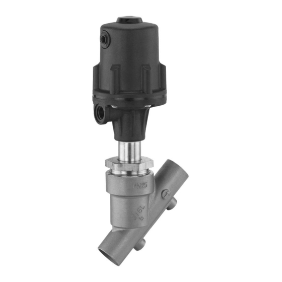
- Page 1 Schrägsitzventil Metall, DN 6 - 80 Angle Seat Globe Valve Metal, DN 6 - 80 ORIGINAL EINBAU- UND MONTAGEANLEITUNG INSTALLATION, OPERATING AND MAINTENANCE INSTRUCTIONS...
-
Page 2: Table Of Contents
Inhaltsverzeichnis Allgemeine Hinweise Voraussetzungen für die einwandfreie Allgemeine Hinweise Funktion des GEMÜ-Ventils: Allgemeine Sicherheitshinweise 2 Sachgerechter Transport und Lagerung Hinweise für Service- und Installation und Inbetriebnahme durch Bedienpersonal eingewiesenes Fachpersonal Warnhinweise Bedienung gemäß dieser Einbau- und Verwendete Symbole Montageanleitung Begriff sbestimmungen Ordnungsgemäße Instandhaltung Vorgesehener Einsatzbereich Auslieferungszustand... -
Page 3: Hinweise Für Service- Und
Hinweise für Service- und Warnhinweise Bedienpersonal Warnhinweise sind, soweit möglich, nach folgendem Schema gegliedert: Die Einbau- und Montageanleitung enthält grundlegende Sicherheitshinweise, die bei SIGNALWORT Inbetriebnahme, Betrieb und Wartung zu beachten sind. Nichtbeachtung kann zur Art und Quelle der Gefahr Folge haben: ®... -
Page 4: Verwendete Symbole
Vorgesehener Verwendete Symbole Einsatzbereich Gefahr durch heiße Oberfl ächen! Das 2/2-Wege-Schrägsitzventil GEMÜ 554 ist für den Einsatz in Gefahr durch ätzende Stoff e! Rohrleitungen konzipiert. Es steuert ein durchfl ießendes Medium indem es durch ein Steuermedium geschlossen oder Hand: Beschreibt allgemeine geöff... -
Page 5: Technische Daten
Technische Daten Ausführungen 0K, 1K, 2K, 3L und 4L gelten nur für Anschlussart Code 80 in Kombination mit Ventilkörperwerkstoff C2 (nur DN 15, 20, 25, 40, 50 und 65 / Antrieb B nicht verfügbar). Betriebsmedium Antriebsdaten Aggressive, neutrale, gasförmige und flüssige Medien, die Kolben- Antriebsgröße Füllvolumen... - Page 6 Druck- / Temperatur-Zuordnung für Schrägsitz-Ventilkörper Zulässige Betriebsüberdrücke in bar bei Temperatur in °C* Anschluss- Werkstoff- Code Code 1, 3C, 3D, 9 (bis DN 50) 16,0 16,0 16,0 13,5 1, 9 (ab DN 65) 10,0 10,0 10,0 1, 9, 17, 37, 60, 63, 3C, 3D 25,0 23,8 21,4...
- Page 7 Antriebsgröße 4L Federkraft geschlossen (NC) min. Steuerdruck in Abhängigkeit vom Betriebsdruck (Durchflussrichtung: mit dem Teller) DN 65 DN 50 DN 40 DN 25 DN 20 DN 15 Betriebsdruck [bar] Betriebsdruck [bar] Betriebsdruck- / Steuerdruckkennlinien - Antriebsgrößen 0, 1, 2, 3, 4 Antriebsgröße 0 Antriebsgröße 1 Antriebsgröße 2...
-
Page 8: Bestelldaten
Baulänge ASME BPE ** nur Steuerfunktion NC Clamp DIN 32676 Reihe B für Rohr EN ISO 1127, Baulänge EN 558, Reihe 1 Clamp DIN 32676 Reihe A für Rohr DIN 11850, GEMÜ 554 GEMÜ 554 Baulänge EN 558, Reihe 1 Antriebe Antriebe Clamp ASME BPE für Rohr ASME BPE,... -
Page 9: Herstellerangaben
Ausführungsart Code Stopfbuchspackung PTFE / PTFE geeignet für den Kontakt mit Lebensmitteln konform gemäß EU-Verordnung 1935/2004 2013 Oberflächengüte nur für Ventilkörperwerkstoff C2 Ra ≤ 0,6 μm (25 μinch) für medienberührte Oberflächen, gemäß ASME BPE SF2 + SF3, innen mechanisch poliert 1903 Ra ≤... -
Page 10: Benötigtes Werkzeug
4 Passendes, funktionsfähiges und sicheres Werkzeug benutzen. Steuermedium- anschluss 2 Funktionsbeschreibung Das fremdgesteuerte 2/2 Wege-Ventil GEMÜ 554 ist ein Metall-Schrägsitzventil mit Durchgangskörper und besitzt einen pneumatischen Kunststoff-Kolbenantrieb. Ventilkörper und Sitzdichtung sind gemäß Datenblatt in verschiedenen Ausführungen erhältlich.Vielfältiges Geräteaufbau Zubehör ist lieferbar, z. B. elektrische Stellungsrückmelder, Pilotventile und... -
Page 11: Montage Und Anschluss
Montage und Anschluss Installationsort: VORSICHT Vor Einbau: Ventil äußerlich nicht stark beanspruchen. Eignung Ventilkörper- und Dichtwerkstoff Installationsort so wählen, dass Ventil entsprechend Betriebsmedium prüfen. nicht als Steighilfe genutzt werden Siehe Kapitel 6 "Technische Daten". kann. Rohrleitung so legen, dass Schub- und 11.1 Montage des Ventils Biegungskräfte, sowie Vibrationen und... -
Page 12: Steuerfunktionen
Montage: Montage bei Clampanschluss: 1. Eignung des Ventils für jeweiligen Bei Montage der Clampanschlüsse Einsatzfall sicherstellen. Das Ventil entsprechende Dichtung zwischen muss für die Betriebsbedingungen Ventilkörper und Rohranschluss einlegen des Rohrleitungssystems (Medium, und mit Klammer verbinden. Die Dichtung Mediumskonzentration, Temperatur sowie die Klammer der Clampanschlüsse und Druck) sowie die jeweiligen sind nicht im Lieferumfang enthalten. -
Page 13: Steuermedium Anschließen
Nur für Regelventile: Steuerfunktion 8 Steuerfunktion Anschlüsse Beidseitig angesteuert (in Ruhestellung Federkraft 2: Steuermedium (Öffnen) geöffnet): geschlossen (NC) Federkraft geöffnet Ruhezustand des Ventils: durch Federkraft 4: Steuermedium (Schließen) (NO) geöffnet. Öffnen und Schließen des Ventils Beidseitig 2: Steuermedium (Öffnen) durch Ansteuern der entsprechenden angesteuert (DA) 4: Steuermedium (Schließen) Beidseitig... -
Page 14: Auswechseln Der Dichtungen
12.2 Auswechseln der Dichtungen Typenschild Antrieb Ventilkörperkennzeichnung RAxxx R002 Auswechseln der Sitzdichtung: RBxxx R004 nicht bei Antriebsgröße B. RCxxx R006 RDxxx R008 Wichtig: RExxx R010 Dichtring 4 bei jeder Demontage / Montage des Antriebs RFxxx R012 austauschen. RGxxx R015 RHxxx R020 1. -
Page 15: Montage Von Zubehör
Vor Reinigung bzw. vor Inbetriebnahme Antriebe B, 0, 1, 2, 3 und 4 der Anlage: Nennweite Drehmomente [Nm] Ventil auf Dichtheit und Funktion prüfen DN 50 (Ventil schließen und wieder öff nen). DN 65 Bei neuen Anlagen und nach DN 80 Reparaturen Leitungssystem bei voll geöff... -
Page 16: Demontage
Hakenschlüssel mit Zapfen 16.1 Demontage zur Entsorgung (Zapfengröße 3 mm) nachziehen für Steuerfunktion 1 (siehe Bilder Seite 15). WARNUNG GEMÜ 554 Antriebsgröße B Antriebsoberteil steht unter Federdruck! ® Gefahr von schwersten Verletzungen oder Tod! Antrieb nur unter Presse öff nen. -
Page 17: Demontage Zur Entsorgung Für Steuerfunktion
3. Verbindungsschrauben 23 zwischen Antriebsoberteil 10 und Antriebsunterteil 25 lösen und entfernen. 3. Antriebsoberteil 10 entnehmen. 4. Presskraft langsam reduzieren. 5. Antriebsoberteil 10 entnehmen. 4. Sechskantmutter 11 von der Spindel 2 lösen und entfernen. Beim Lösen der Sechskantmutter die Spindel mit geeignetem Werkzeug fi... -
Page 18: Hinweise
5. Antriebskolben 20 von Spindel 2 entfernen. Rücksendung Ventil reinigen. Rücksendeerklärung bei GEMÜ anfordern. Rücksendung nur mit vollständig ausgefüllter Rücksendeerklärung. 16.3 Demontage zur Entsorgung für Steuerfunktion 3 Ansonsten erfolgt keine Gutschrift bzw. keine 1. Antrieb A demontieren (siehe Kapitel Erledigung der Reparatur 12.1 "Demontage Antrieb"). -
Page 19: Fehlersuche / Störungsbehebung
Fehlersuche / Störungsbehebung Fehler Möglicher Grund Fehlerbehebung Steuermedium entweicht aus Entlüftungsbohrung* Antrieb austauschen und Steuermedium auf bei Steuerfunktion NO / Steuerkolben undicht Verschmutzungen untersuchen Anschluss 2* bei Steuerfunktion NC Steuermedium entweicht Antrieb austauschen und Steuermedium auf Spindelabdichtung undicht aus Leckagebohrung* Verschmutzungen untersuchen Betriebsmedium entweicht Stopfbuchspackung defekt... -
Page 20: Schnittbild Und Ersatzteile
Abdeckkappe Anschluss 4 / Entlüftungsbohrung bei Steuerfunktion Anschluss 2 / Entlüftungsbohrung bei Steuerfunktion Leckagebohrung Pos. Benennung Bestellbezeichnung Ventilkörper K514... Dichtring 554...SVS... Sitzdichtung (nicht bei Antriebsgröße B) Antrieb 9554... Überwurfmutter Spindel Ventilteller Mutter / Tellerscheibe / Regelkegel Scheibe 20 / 44... -
Page 21: Einbauerklärung
29.12.2009 Projektnummer: SV-Pneum-2009-12 Handelsbezeichnung: Typ 554 Es wird erklärt, dass die folgenden grundlegenden Anforderungen der Maschinenrichtlinie 2006/42/EG erfüllt sind: 1.1.3.; 1.1.5.; 1.1.7.; 1.2.1.; 1.3.; 1.3.2.; 1.3.3.; 1.3.4.; 1.3.7.; 1.3.9.; 1.5.3.; 1.5.5.; 1.5.6.; 1.5.7.; 1.5.8.; 1.5.9.; 1.6.5.; 2.1.1.; 3.2.1.; 3.2.2.; 3.3.2.; 3.4.4.; 3.6.3.1.; 4.1.2.1.; 4.1.2.3.; 4.1.2.4.; 4.1.2.5.; 4.1.2.6. a); 4.1.2.6. b);... -
Page 22: Eu-Konformitätserklärung
GEMÜ Gebr. Müller Apparatebau GmbH & Co. KG Fritz-Müller-Straße 6-8 D-74653 Ingelfingen erklären, dass unten aufgeführte Armaturen die Sicherheitsanforderungen der Druckgeräte- richtlinie 2014/68/EU erfüllen. Benennung der Armaturen - Typenbezeichnung Sitzventil GEMÜ 554 Benannte Stelle: TÜV Rheinland Industrie Service GmbH Nummer: 0035 Zertifikat-Nr.: 01 202 926/Q-02 0036... - Page 23 Contents Declaration of incorporation EU Declaration of conformity General information General safety information General information Information for service and operating personnel Prerequisites to ensure that the GEMÜ valve Warning notes functions correctly: Symbols used Correct transport and storage Defi nition of terms Installation and commissioning by trained Intended area of use personnel...
-
Page 24: Information For Service And Operating Personnel
Information for service Warning notes and operating personnel Wherever possible, warning notes are organised according to the following The installation, operating and maintenance scheme: instructions contain fundamental safety information that must be observed SIGNAL WORD during commissioning, operation, and maintenance. Non-compliance with these Type and source of the danger instructions may cause: ®... -
Page 25: Symbols Used
Intended area of use Symbols used The GEMÜ 554 2/2-way angle seat globe Danger - hot surfaces! valve is designed for installation in piping systems. It controls a fl owing medium by being closed or opened by a control Danger - corrosive materials! medium. -
Page 26: Technical Data
Technical data Versions 0K, 1K, 2K, 3L and 4L are only valid for connection code 80 in combination with valve body material C2 (only DN 15, 20, 25, 40, 50 and 65 / actuator B not available). Technical data / Actuator Working medium Corrosive, inert, gaseous and liquid media which have no Actuator size... - Page 27 Pressure / temperature correlation for angle seat globe valve bodies Max. allowable operating pressures in bar at temperature °C* Material Connection code code 1, 3C, 3D, 9 (up to DN 50) 16.0 16.0 16.0 13.5 1, 9 (from DN 65) 10.0 10.0 10.0...
- Page 28 Actuator size 4L Normally closed (NC) Min. control pressure dependent on operating pressure (Flow direction: over the seat) DN 65 DN 50 DN 40 DN 25 DN 20 DN 15 Operating pressure [bar] Betriebsdruck [bar] Operating pressure / Control pressure characteristic - Actuator sizes 0, 1, 2, 3, 4 Actuator size 0 Actuator size 1 Actuator size 2...
-
Page 29: Order Data
"water hammer" Clamp connections ** only control function NC Clamps ASME BPE for pipe ASME BPE, length ASME BPE GEMÜ 554 GEMÜ 554 Actuators Actuators Clamps DIN 32676 series B for pipe EN ISO 1127, B, 0, 0K, 1, 1K,... -
Page 30: Manufacturer's Information
Version Code Gland packing PTFE / PTFE suitable for contact with food according to EU Regulation 1935/2004 2013 Surface finish for valve body material C2 Ra ≤ 0.6 μm (25 μinch) for process contact surfaces, in accordance with ASME BPE SF2 + SF3, mechanically polished internal 1903 Ra ≤... -
Page 31: Tools Required
Control medium connector 2 Functional description The GEMÜ 554 pneumatically operated 2/2- way valve is a metal angle seat globe valve with a straight through body and a plastic piston actuator. The valve bodies and the seat seals are available in various designs as shown in the data sheet. -
Page 32: Installation And Connection
Installation and connection Installation location: CAUTION Prior to installation: Ensure that valve body and seal material Do not apply external force to the valve. are appropriate and compatible to handle Choose the installation location so that the working medium. the valve cannot be used as a foothold See chapter 6 "Technical data". -
Page 33: Control Functions
Installation: Installation - Clamp connections: 1. Ensure the suitability of the valve for When assembling clamp connections, each respective use. The valve must insert a gasket between the body clamp be appropriate for the piping system and the adjacent piping clamp and join operating conditions (medium, medium them using the appropriate clamp fi... -
Page 34: Connecting The Control Medium
Only for control valves: Control function 8 Control function Connectors Double acting (normally open): Normally closed (NC) 2: Control medium (open) Valve resting position: opened by spring Normally open (NO) 4: Control medium (close) force. The valve is opened and closed 2: Control medium (open) Double acting (DA) by activating the respective control... -
Page 35: Replacement Of Seals
12.2 Replacement of seals Product label of Valve body marking actuator Replacement of seat seal: not for RAxxx R002 actuator size B. RBxxx R004 RCxxx R006 Important: RDxxx R008 Replace gasket 4 during every RExxx R010 actuator disassembly / assembly. RFxxx R012 RGxxx... -
Page 36: Mounting Of Accessories
Prior to cleaning or commissioning the Actuators 0K, 1K, 2K, 3L and 4L plant: Nominal size Torques [Nm] Check the tightness and the function of DN 15 the valve (close and reopen the valve). DN 20 If the plant is new rinse the piping system DN 25 with a fully opened valve (to remove any DN 40... -
Page 37: Disassembly
B retighten with a pin wrench media. (pin size 3 mm) (see pictures on page 33). Note: Once disassembled, the parts GEMÜ 554 Actuator size B must not be re-assembled! 16.1 Disassembly for disposal for control function 1 WARNING Actuator top is under spring pressure. -
Page 38: Disassembly For Disposal For Control Function
3. Undo and remove the connecting bolts 23 between the actuator top 10 and the actuator base 25. 3. Remove actuator top 10. 4. Slowly reduce pressing force. 5. Remove actuator top 10. 4. Undo and remove the hexagon nut 11 from the spindle 2. -
Page 39: Returns
5. Remove piston 20 from spindle 2. Returns Clean the valve. Request a goods return declaration form from GEMÜ. 16.3 Disassembly for disposal for control Returns must be made with a completed function 3 declaration of return. If not completed, GEMÜ cannot process 1. -
Page 40: Troubleshooting / Fault Clearance
Troubleshooting / Fault clearance Fault Possible cause Fault clearance Control medium escapes from vent hole* Replace actuator and check control medium for (for control function NO) Control piston leaking impurities or from connector 2* (for control function NC) Control medium escapes Replace actuator and check control medium for Spindle seal leaking from leak detection hole*... -
Page 41: Sectional Drawing And Spare Parts
NC Leak detection hole Item Name Order description Valve body K514... Gasket 554...SVS... Seat seal (not for actuator size B) Actuator 9554... Union nut Spindle Valve plug Nut / retaining washer / regulating cone Washer... -
Page 42: Declaration Of Incorporation
December 29, 2009 Project number: SV-Pneum-2009-12 Commercial name: Type 554 We hereby declare that the following essential requirements of the Machinery Directive 2006/42/EC have been fulfilled: 1.1.3.; 1.1.5.; 1.1.7.; 1.2.1.; 1.3.; 1.3.2.; 1.3.3.; 1.3.4.; 1.3.7.; 1.3.9.; 1.5.3.; 1.5.5.; 1.5.6.; 1.5.7.; 1.5.8.; 1.5.9.;... -
Page 43: 22 Eu Declaration Of Conformity
D-74653 Ingelfingen declare that the equipment listed below complies with the safety requirements of the Pressure Equipment Directive 2014/68/EU. Description of the equipment - product type Globe valve GEMÜ 554 Notified body: TÜV Rheinland Industrie Service GmbH Number: 0035 Certificate no.:... - Page 44 GEMÜ Gebr. Müller Apparatebau GmbH & Co. KG · Fritz-Müller-Str. 6-8 · D-74653 Ingelfi ngen-Criesbach Telefon +49(0)7940/123-0 · Telefax +49(0)7940/123-192 · info@gemue.de · www.gemu-group.com...
Need help?
Do you have a question about the 554 and is the answer not in the manual?
Questions and answers