Table of Contents
Advertisement
Quick Links
Advertisement
Table of Contents

Related Manuals for Ditel DN109/NB


Summary of Contents for Ditel DN109/NB
- Page 1 TECHNICAL MANUAL LARGE DISPLAYS DN109/NB - DN119/NB - DN189/NB - DN129/NB...
- Page 2 TECHNICAL MANUAL LARGE DISPLAYS DN109/NB - DN119/NB - DN189/NB - DN129/NB INDEX 18-1 19 INTRODUCTION ....................... 19-1 20 GENERAL CHARACTERISTICS ..................20-1 Display ..........................20-1 DN109 ......................... 20-1 DN119 ......................... 20-1 DN189 ......................... 20-1 DN129 ......................... 20-2 Weight and consumption ....................20-3 DN109 .........................
- Page 3 TECHNICAL MANUAL LARGE DISPLAYS DN109/NB - DN119/NB - DN189/NB - DN129/NB INDEX 18-2 24 ETHERNET BUS COMMUNICATION ................24-1 Ethernet adjustments ..................... 24-1 MODBUS/TCP Protocol ....................24-2 MODBUS Functions ....................24-2 Register Writing ......................24-9 Coil Writing ........................ 24-12 Reading of registers and coils .................. 24-12 TCP/IP Protocol ......................
-
Page 4: Technical Manual
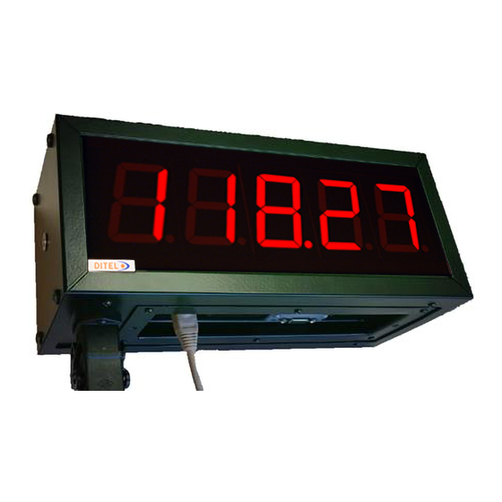
TECHNICAL MANUAL LARGE DISPLAYS DN109/NB - DN119/NB - DN189/NB - DN129/NB CHAPTER 19 INTRODUCTION 19-1 19 INTRODUCTION DN/NB series displays are industrial led visualizers presenting relevant numerical data, allowing long distance viewing. Main features depending on chosen model are: 2 to 10 digits. -
Page 5: General Characteristics
TECHNICAL MANUAL LARGE DISPLAYS DN109/NB - DN119/NB - DN189/NB - DN129/NB CHAPTER 20 GENERAL CHARACTERISTICS 20-1 20 GENERAL CHARACTERISTICS Display DN109 Power supply ..........80 a 240 VAC 50/60Hz. Option 24VDC. Consumption ..........See 20.2.1. Display ............7 segments 57 mm + decimal dot .............. - Page 6 TECHNICAL MANUAL LARGE DISPLAYS DN109/NB - DN119/NB - DN189/NB - DN129/NB CHAPTER 20 GENERAL CHARACTERISTICS 20-2 DN129 Power supply ..........80 a 240 VAC 50/60Hz. Option 24VDC. Consumption ..........See 20.2.4. Display ............7 segments 250 mm + decimal dot ..............
- Page 7 TECHNICAL MANUAL LARGE DISPLAYS DN109/NB - DN119/NB - DN189/NB - DN129/NB CHAPTER 20 GENERAL CHARACTERISTICS 20-3 Weight and consumption DN109 Ref. W (kg) C (W) Ref. W (kg) C (w) Ref. W (kg) C (W) DN109/3S DN109/3S+TL 11,9 DN109/3S+TV DN109/3D...
- Page 8 TECHNICAL MANUAL LARGE DISPLAYS DN109/NB - DN119/NB - DN189/NB - DN129/NB CHAPTER 20 GENERAL CHARACTERISTICS 20-4 DN189 Ref. W (kg) C (W) Ref. W (kg) C (W) 17,3 17,3 DN189/2S DN189/2S+TV 29,8 29,8 DN189/2D DN189/2D+TV 23,4 23,4 DN189/3S DN189/3S+TV 42,2...
-
Page 9: Sizes And Dimensions
TECHNICAL MANUAL LARGE DISPLAYS DN109/NB - DN119/NB - DN189/NB - DN129/NB CHAPTER 20 GENERAL CHARACTERISTICS 20-5 Sizes and dimensions DN109 and DN119 Ref. Ref. DN109/3S DN109/3S+T DN109/4S DN109/4S+T DN109/5S DN109/5S+T DN109/6S DN109/6S+T DN109/7S DN109/7S+T DN109/8S DN109/8S+T DN109/9S DN109/9S+T DN109/10S DN109/10S+T... - Page 10 TECHNICAL MANUAL LARGE DISPLAYS DN109/NB - DN119/NB - DN189/NB - DN129/NB CHAPTER 20 GENERAL CHARACTERISTICS 20-6 DN129 and DN189 Ref. Ref. DN189/2S DN189/2S+TV DN189/3S DN189/3S+TV DN189/4S DN189/4S+TV DN189/5S DN189/5S+TV 1140 DN189/6S DN189/6S+TV 1300 DN189/7S 1140 DN189/7S+TV 1460 DN189/8S 1300 DN189/8S+TV...
-
Page 11: Installation
TECHNICAL MANUAL LARGE DISPLAYS DN109/NB - DN119/NB - DN189/NB - DN129/NB CHAPTER 21 INSTALLATION 21-1 21 INSTALLATION DN1x9 installation is easy by complying the following rules. Choose carefully an installation place that complies with environmental requirements and avoid vibration. Choose the display IP level according to place requirements. IP65 installation details can be found at 21.3. -
Page 12: Power Supply Wiring
TECHNICAL MANUAL LARGE DISPLAYS DN109/NB - DN119/NB - DN189/NB - DN129/NB CHAPTER 21 INSTALLATION 21-2 General connectors: • ETH. RJ45 Ethernet. • USB. Micro USB-A. • SERIAL. DB-9 connector male. See 21.4. • S1-4. Probe connectors 1 to 4. E.g. for T & HR sensing. -
Page 13: Serial Line Connection
TECHNICAL MANUAL LARGE DISPLAYS DN109/NB - DN119/NB - DN189/NB - DN129/NB CHAPTER 21 INSTALLATION 21-3 Procedure: 17. Withdraw the 6 yellow highlighted screws from display. Save it. See below picture. 18. On the cover, pass cables to be connected through glands provided. - Page 14 TECHNICAL MANUAL LARGE DISPLAYS DN109/NB - DN119/NB - DN189/NB - DN129/NB CHAPTER 21 INSTALLATION 21-4 RS-232 connection between a PC and DN-1x9 display Use a standard RS-232 line. Maximum recommended length is 15 m (9.600 bps). Use shielded cable and connect shield to pin 9. Please avoid near disturbances.
-
Page 15: Ethernet Line Connection
TECHNICAL MANUAL LARGE DISPLAYS DN109/NB - DN119/NB - DN189/NB - DN129/NB CHAPTER 21 INSTALLATION 21-5 Ethernet line connection Ethernet connection is done by a RJ-45 connector, located at the bottom of the display. The display can be connected directly to a computer or to a network, usually using a switch or hub module. - Page 16 TECHNICAL MANUAL LARGE DISPLAYS DN109/NB - DN119/NB - DN189/NB - DN129/NB CHAPTER 22 INITIALIZATION 22-1 22 INITIALIZATION Start-up Before connecting to power supply please be sure all the above mentioned advices are done. During the boot process, the different initialization stages will be indicated on the display,...
- Page 17 TECHNICAL MANUAL LARGE DISPLAYS DN109/NB - DN119/NB - DN189/NB - DN129/NB CHAPTER 22 INITIALIZATION 22-2 Configuration with “Display Discoverer” Fig. 92: "Display Discoverer" software window. By default, the viewer comes from factory with IP address 10.30.90.10. To change the IP you have to select the default IP and press “Change IP”...
-
Page 18: Display Configuration
TECHNICAL MANUAL LARGE DISPLAYS DN109/NB - DN119/NB - DN189/NB - DN129/NB CHAPTER 22 INITIALIZATION 22-3 IMPORTANT: If several new devices are received for installation, keep in mind that they will all come configured with the same IP address. Therefore, prior to its configuration, the IP of some equipment must be changed individually to avoid duplication of addresses. - Page 19 TECHNICAL MANUAL LARGE DISPLAYS DN109/NB - DN119/NB - DN189/NB - DN129/NB CHAPTER 22 INITIALIZATION 22-4 Overview Fig. 94: Initial window. The initial screen of the server shows us a vision of the basic information of the viewer and the necessary buttons to scroll through the different configuration options.
-
Page 20: Global Settings
TECHNICAL MANUAL LARGE DISPLAYS DN109/NB - DN119/NB - DN189/NB - DN129/NB CHAPTER 22 INITIALIZATION 22-5 Global Settings Fig. 95: Global Settings Window. Various parameters and options are modified on the global settings window. Such modifications will also affect the configurable parameters of the web server and subsequent configuration windows. - Page 21 TECHNICAL MANUAL LARGE DISPLAYS DN109/NB - DN119/NB - DN189/NB - DN129/NB CHAPTER 22 INITIALIZATION 22-6 33. Selecting “FULL DIGIT” left digit is used only to show negative sign “-“. Selecting “HALF DIGIT” left digit takes the value “-“ or “-1”, so the capacity to display negative numbers is increased.
-
Page 22: Network Settings
TECHNICAL MANUAL LARGE DISPLAYS DN109/NB - DN119/NB - DN189/NB - DN129/NB CHAPTER 22 INITIALIZATION 22-7 Network Settings Fig. 97: Ethernet network settings. Parameters related to the connectivity of the display are configured on the network settings screen: 19. Modifies the name assigned to the display. - Page 23 TECHNICAL MANUAL LARGE DISPLAYS DN109/NB - DN119/NB - DN189/NB - DN129/NB CHAPTER 22 INITIALIZATION 22-8 WIFI Settings Fig. 98: Wifi Settings. In the WIFI settings, the parameters related to the wireless connectivity of the display are configured. 23. STATION Mode: Set the name of the WIFI Network to connect to.
- Page 24 TECHNICAL MANUAL LARGE DISPLAYS DN109/NB - DN119/NB - DN189/NB - DN129/NB CHAPTER 22 INITIALIZATION 22-9 ATTENTION: It is necessary to check that the IP address to be applied is not occupied. 31. Set network mask. 32. Set gateway. 33. Set DNS. In case DNS is not set correctly, you must configure the SNTP server with your IP and not with your domain.
-
Page 25: Communication Settings
TECHNICAL MANUAL LARGE DISPLAYS DN109/NB - DN119/NB - DN189/NB - DN129/NB CHAPTER 22 INITIALIZATION 22-10 Communication Settings Communication Settings at chapter 22. COLOR Settings Fig. 100: Web server color settings window. In the color settings screen, the parameters related to the color shown by the display are configured. - Page 26 TECHNICAL MANUAL LARGE DISPLAYS DN109/NB - DN119/NB - DN189/NB - DN129/NB CHAPTER 22 INITIALIZATION 22-11 26. Set the activation value of R0. 27. Select the desired event for R0: G. NONE: The event is activated strictly following what is defined in the activation condition.
- Page 27 TECHNICAL MANUAL LARGE DISPLAYS DN109/NB - DN119/NB - DN189/NB - DN129/NB CHAPTER 22 INITIALIZATION 22-12 DELAY HYSTERESIS Fig. 101: Graphic explanation of delay and hysteresis...
-
Page 28: Work Operation
TECHNICAL MANUAL LARGE DISPLAYS DN109/NB - DN119/NB - DN189/NB - DN129/NB CHAPTER 23 WORK OPERATION 23-1 23 WORK OPERATION The notation for numerical values used in this manual is as follows: • Hexadecimal numbers: Number followed by “h”. • Decimal numbers: Number followed by “d”. - Page 29 TECHNICAL MANUAL LARGE DISPLAYS DN109/NB - DN119/NB - DN189/NB - DN129/NB CHAPTER 23 WORK OPERATION 23-2 Accepted ASCII Character Sequences The display accepts alphanumeric ASCII characters that can be represented in a 7- segment. The valid characters accepted by the display are the following: Carácter...
- Page 30 TECHNICAL MANUAL LARGE DISPLAYS DN109/NB - DN119/NB - DN189/NB - DN129/NB CHAPTER 24 ETHERNET COMMUNICATION 24-1 24 ETHERNET BUS COMMUNICATION Ethernet adjustments Fig. 102: Ethernet communications web server winndow. 13. Drop-down menu to select the protocol to be used: Available protocols TCP, UDP y MODBUS/TCP.
-
Page 31: Modbus/Tcp Protocol
TECHNICAL MANUAL LARGE DISPLAYS DN109/NB - DN119/NB - DN189/NB - DN129/NB CHAPTER 24 ETHERNET COMMUNICATION 24-2 15. Allows to select an end of frame. It is used as an enabler; the display will only show the data to which the end of the chosen frame is added. Selecting NONE disables this feature. - Page 32 TECHNICAL MANUAL LARGE DISPLAYS DN109/NB - DN119/NB - DN189/NB - DN129/NB CHAPTER 24 ETHERNET COMMUNICATION 24-3 This section details how the information is structured at the protocol level in order to debug communication problems with a MODBUS frame analyzer. If you already have knowledge of this protocol, you can go directly to section 24.2.2...
- Page 33 TECHNICAL MANUAL LARGE DISPLAYS DN109/NB - DN119/NB - DN189/NB - DN129/NB CHAPTER 24 ETHERNET COMMUNICATION 24-4 • Write Single Coil: It is used to assign the ON/OFF state to a Coil. The structure of this function is presented below: Request...
- Page 34 TECHNICAL MANUAL LARGE DISPLAYS DN109/NB - DN119/NB - DN189/NB - DN129/NB CHAPTER 24 ETHERNET COMMUNICATION 24-5 • Write Multiple Coils: It is used to simultaneously assign the status of several consecutive addressing Coils. The structure of this function is presented below:...
- Page 35 TECHNICAL MANUAL LARGE DISPLAYS DN109/NB - DN119/NB - DN189/NB - DN129/NB CHAPTER 24 ETHERNET COMMUNICATION 24-6 • Read Holding Registers: Allows you to view the content of the desired registers. The structure of this function is presented below: Request Function code...
- Page 36 TECHNICAL MANUAL LARGE DISPLAYS DN109/NB - DN119/NB - DN189/NB - DN129/NB CHAPTER 24 ETHERNET COMMUNICATION 24-7 • Write Single Register: It is used to assign the value to only one register. The structure of this function is presented below: Request...
- Page 37 TECHNICAL MANUAL LARGE DISPLAYS DN109/NB - DN119/NB - DN189/NB - DN129/NB CHAPTER 24 ETHERNET COMMUNICATION 24-8 • Write Multiple Registers: It is used to assign the value to several registers simultaneously. The structure of this function is presented below: Request...
- Page 38 TECHNICAL MANUAL LARGE DISPLAYS DN109/NB - DN119/NB - DN189/NB - DN129/NB CHAPTER 24 ETHERNET COMMUNICATION 24-9 Register Writing The different registers of the display allow interaction in different ways, depending on the address to which it is written, the following registers are distinguished: •...
- Page 39 TECHNICAL MANUAL LARGE DISPLAYS DN109/NB - DN119/NB - DN189/NB - DN129/NB CHAPTER 24 ETHERNET COMMUNICATION 24-10 Fig. 103: Frame in MODBUS/TCP to display the value "-3270". These frames show the sending and response explained in the previous section. 24.2.2.2 Register 06.
- Page 40 TECHNICAL MANUAL LARGE DISPLAYS DN109/NB - DN119/NB - DN189/NB - DN129/NB CHAPTER 24 ETHERNET COMMUNICATION 24-11 Fig. 104: Message in MODBUS/TCP to send the value "-3270". These frames show the sending and response explained in the previous section. 24.2.2.4 Register 14.
- Page 41 TECHNICAL MANUAL LARGE DISPLAYS DN109/NB - DN119/NB - DN189/NB - DN129/NB CHAPTER 24 ETHERNET COMMUNICATION 24-12 Fig. 105: Message in MODBUS/TCP to send the characters "E 523". As can be seen, as many registers as necessary are written. In this case, since the number of characters is 5 (odd), 3 registers must be used, and the last byte must be set to 00h.
-
Page 42: Tcp/Ip Protocol
TECHNICAL MANUAL LARGE DISPLAYS DN109/NB - DN119/NB - DN189/NB - DN129/NB CHAPTER 24 ETHERNET COMMUNICATION 24-13 “Read The frames necessary to carry out these functions are included in section 24.2.1, “Read Holding Coils” and Registers”, respectively. TCP/IP Protocol To use the TCP/IP protocol, the communication port must be properly configured (See section 24.1). -
Page 43: Udp Protocol
TECHNICAL MANUAL LARGE DISPLAYS DN109/NB - DN119/NB - DN189/NB - DN129/NB CHAPTER 24 ETHERNET COMMUNICATION 24-14 UDP Protocol The functionality of the parameters explained in the previous section (protocol TCP/IP) also applies to the UDP protocol. -
Page 44: Wifi Communication
TECHNICAL MANUAL LARGE DISPLAYS DN109/NB - DN119/NB - DN189/NB - DN129/NB CHAPTER 25 WIFI COMMUNICATION 25-1 25 WIFI COMMUNICATION The bandwidth of WIFI communication is reduced compared to the wired connection. As a result, the setup experience will always be smoother via cable. This difference will not be noticeable once the device is configured and dedicated exclusively to data visualization. - Page 45 TECHNICAL MANUAL LARGE DISPLAYS DN109/NB - DN119/NB - DN189/NB - DN129/NB CHAPTER 26 SERIAL COMMUNICATION 26-1 26 SERIAL BUS COMMUNICATION This section includes the settings of the web server of the display and the operation of the available protocols in case of communication through the serial bus.
- Page 46 TECHNICAL MANUAL LARGE DISPLAYS DN109/NB - DN119/NB - DN189/NB - DN129/NB CHAPTER 26 SERIAL COMMUNICATION 26-2 Order Function Display value Tare value High peak value Low peak value Peak to peak value Total value For more information on the function of these commands, refer to the RS outputs manual for KOSMOS indicators.
- Page 47 TECHNICAL MANUAL LARGE DISPLAYS DN109/NB - DN119/NB - DN189/NB - DN129/NB CHAPTER 26 SERIAL COMMUNICATION 26-3 41. Select the transfer rate in bits/s. 42. Select the number of bytes per character: You can select 7 or 8 bits. If the MODBUS RTU protocol is used, it cannot be modified, the value is set to 8 bits.
-
Page 48: Modbus Rtu Protocol
TECHNICAL MANUAL LARGE DISPLAYS DN109/NB - DN119/NB - DN189/NB - DN129/NB CHAPTER 26 SERIAL COMMUNICATION 26-4 Fig. 109: Diagram of use of the MSG.OFFSET and MSG.CURSOR parameters. 48. When modifying any parameter, the button is enabled to send the new information to the display. -
Page 49: Ascii Protocol
TECHNICAL MANUAL LARGE DISPLAYS DN109/NB - DN119/NB - DN189/NB - DN129/NB CHAPTER 26 SERIAL COMMUNICATION 26-5 Example: To send “HELLO” (48h 4Fh 4Ch 41h) the following frames are set: Fig. 111: Frames sent and received to display "HELLO" by MODBUS RTU... - Page 50 TECHNICAL MANUAL LARGE DISPLAYS DN109/NB - DN119/NB - DN189/NB - DN129/NB CHAPTER 26 SERIAL COMMUNICATION 26-6 Displays with the color option 58h (o 78h) Red digits 58h (o 78h) Green digits 58h (o 78h) Yellow digits 58h (o 78h) Orange digits The mentioned control commands (blink and color) should be placed at the end of the frame.
- Page 51 TECHNICAL MANUAL LARGE DISPLAYS DN109/NB - DN119/NB - DN189/NB - DN129/NB CHAPTER 26 SERIAL COMMUNICATION 26-7 • Display address: 14 • Header: 02h AL AH • End block: CR LF • MSG. OFFSET: 1 (To display only the numerical value) •...
-
Page 52: Display Update
TECHNICAL MANUAL LARGE DISPLAYS DN109/NB - DN119/NB - DN189/NB - DN129/NB CHAPTER 27 UPDATE 27-1 27 DISPLAY UPDATE Should you need to update the firmware, please download MicroBoot program form (https://www.ditel.es/descargas) and proceed as follows . IMPORTANT: The update must be done through a wired ETHERNET connection Steps to do the firmware upload: 7. - Page 53 TECHNICAL MANUAL LARGE DISPLAYS DN109/NB - DN119/NB - DN189/NB - DN129/NB CHAPTER 27 UPDATE 27-2 If the update takes too long to start, cancel the process, check the IP configured in the MicroBoot, the Ethernet cable and the Firewall rules and repeat the firmware update process.
- Page 54 TECHNICAL MANUAL LARGE DISPLAYS DN109/NB - DN119/NB - DN189/NB - DN129/NB ANNEX I ANNEX 1: Send information with “Hercules” for TCP, UDP and serial communication When carrying out the communication using the "Hercules" program, certain aspects must be taken into account so as not to make mistakes when sending values in decimal or hexadecimal.
-
Page 55: Parity = None
TECHNICAL MANUAL LARGE DISPLAYS DN109/NB - DN119/NB - DN189/NB - DN129/NB ANNEX I Example of web server configuration for TCP: 7. “Global Settings” Window., DATA PORT = ETHERNET. 8. “Network Settings” window, set the right network parameters, in this case IP Addr = 10.30.90.12 like in “Hercules”. - Page 56 TECHNICAL MANUAL LARGE DISPLAYS DN109/NB - DN119/NB - DN189/NB - DN129/NB ANNEX II ANNEX 2: Send information with “QModMaster” for MODBUS TCP and MODBUS RTU When communicating over MODBUS using QModMaster there are few differences to work over RTU or TCP.
- Page 57 TECHNICAL MANUAL LARGE DISPLAYS DN109/NB - DN119/NB - DN189/NB - DN129/NB ANNEX II Data Format: This drop-down menu allows you to change the contents of the registers to the desired system. It is very useful to enter data in the most comfortable way possible, if there is already data written, the program converts it automatically.
- Page 58 TECHNICAL MANUAL LARGE DISPLAYS DN109/NB - DN119/NB - DN189/NB - DN129/NB ANNEX II 6. “Communication Settings” windows : • ADDRESS = 1. • PROTOCOL = MODBUS RTU. • INTERFACE = RS232. • BAUDRATE = 19200 • PARITY = NONE •...
- Page 59 TECHNICAL MANUAL LARGE DISPLAYS DN109/NB - DN119/NB - DN189/NB - DN129/NB ANNEX III ANNEX 3: Configure and use function blocks to send information using a PLC. The following examples has been done using a Siemens PLC “CPU 1512 SP-1 PN”.
- Page 60 TECHNICAL MANUAL LARGE DISPLAYS DN109/NB - DN119/NB - DN189/NB - DN129/NB ANNEX III Second, the blocks and variables, used to generate and send a registers writing message, are shown. Fig. 116: Generation of the content of the registers to be sent...
- Page 61 TECHNICAL MANUAL LARGE DISPLAYS DN109/NB - DN119/NB - DN189/NB - DN129/NB ANNEX III Finally, the blocks and variables used to generate and send a register reading message are shown. Fig. 117: Reading of response registers. It is noticed that the block is the same “Modbus_Master”. By changing the input values, you configure it to be a write or read message, as well as you can configure the number of registers or their location.
- Page 62 TECHNICAL MANUAL LARGE DISPLAYS DN109/NB - DN119/NB - DN189/NB - DN129/NB ANNEX III MODBUS_TCP: The modules for “Modbus_master” of MODBUS_TCP are the same as for RTU. These blocks initiate communication via MODBUS_TCP. It is necessary to set the variable “MBTCP:Ethernet” correctly.
- Page 63 TECHNICAL MANUAL LARGE DISPLAYS DN109/NB - DN119/NB - DN189/NB - DN129/NB ANNEX III UDP: Blocks downloaded from the Siemens website are used to communicate in UDP. Specifically, “S7-1200/S7-1500” (LOpenUserComm_Udp). Fig. 119: "LOpenUserComm_Udp" block udsed for UDP communication. The mentioned module is in charge of carrying out the configuration automatically once the inputs have been set the desired way.
- Page 64 TECHNICAL MANUAL LARGE DISPLAYS DN109/NB - DN119/NB - DN189/NB - DN129/NB ANNEX III RELAY: To activate the relays or the flashing, Modbus must be used. In our case we use the module shown above for Modbus_TCP. The difference is clearly visible, since in this case we work on the address “MB_DATA_ADDR”...
-
Page 65: Declaración De Conformidad
DECLARACIÓN DE CONFORMIDAD CONFORMITY DECLARATION Diseños y Tecnología S.A. Xarol, 6B P.I. Les Guixeres 08915 Badalona España As constructor of the equipment’s DITEL: Model: DN109.NB all versions. Model: DN119.NB all versions. Model: DN129.NB all versions. Model: DN189.NB all versions. We declare under our sole responsibility than the aforementioned products comply with the following European directives: 2014/35/UE LVD.
Need help?
Do you have a question about the DN109/NB and is the answer not in the manual?
Questions and answers