
Subscribe to Our Youtube Channel
Related Manuals for Ditel DT-203 Series


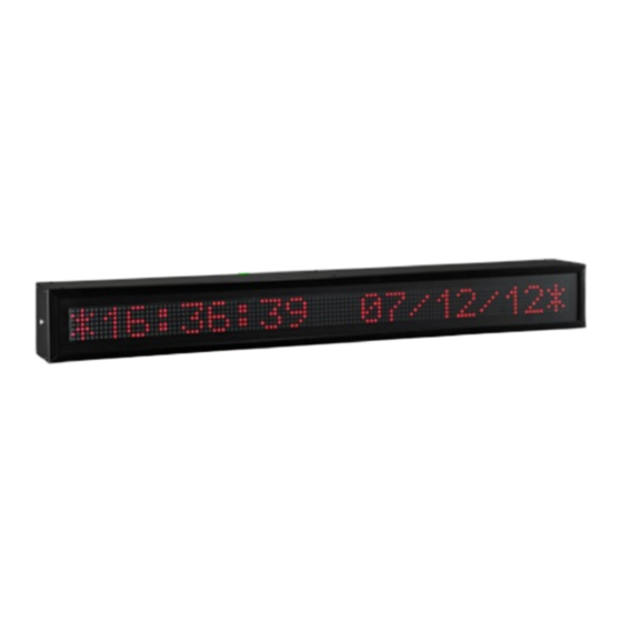
Summary of Contents for Ditel DT-203 Series
- Page 1 OPERATIONAL MANUAL FOR PROFINET DISPLAY SERIES DT-203NN, DT-105NN AND DT-110NN MT-DT_NN_EN_20190405...
- Page 2 CHAPTER 1 INTRODUCTION Index Index ..............................1-1 INTRODUCTION ........................1-2 GENERAL CHARACTERISTICS....................2-1 Electrical characteristics of the displays ................2-1 2.1.1 Electrical characteristics of the DT-203 displays............2-1 2.1.2 Electrical characteristics of the DT-105 displays............2-1 2.1.3 Electrical characteristics of the DT-110 displays............2-1 Weight and power consumption.
- Page 3 CHAPTER 1 INTRODUCTION 1 INTRODUCTION The alphanumerical displays series DT-203NN, DT-105NN and DT-110NN, are industrial displays controled by Profinet network. One of its main characteristics is the height of the characters: DT-203NN: 30mm, readable from up to 15m. DT-105NN: 50mm, readable from up to 25m. DT-110NN: 100mm, readable from up to 50m As with other display series, the DT-NN is available in one or two-sided versions, which provides multiple solutions and installation possibilities.
-
Page 4: General Characteristics
CHAPTER 2 GENERAL CHARACTERISTICS 2 GENERAL CHARACTERISTICS. 2.1 Electrical characteristics of the displays 2.1.1 Electrical characteristics of the DT-203 displays. Supply Voltage........... 100 to 240 VAC 50/60Hz or 24VDC option. Consumption ..........See section 2.2. Display ............7x5 Dot matrix of 30mm high.............. - Page 5 CHAPTER 2 GENERAL CHARACTERISTICS 2.2 Weight and power consumption. Exterior option use column h(VA) Reference Weight Power Power Reference Weight Power Power (kg) (VA) h (VA) (kg) (VA) h (VA) DT-105/1S-6 DT-110/1S-6 DT-105/1D-6 DT-110/1D-6 DT-105/1S-13 DT-110/1S-13 DT-105/1D-13 DT-110/1D-13 13,5 DT-105/1S-20 DT-110/1S-20 DT-105/1D-20 DT-110/1D-20...
- Page 6 CHAPTER 2 GENERAL CHARACTERISTICS Reference Weight Power Power Reference Weight Power Power (kg) (VA) h (VA) (kg) (VA) h (VA) DT-105/5D-20 DT-110/8D-6 DT-105/6S-6 DT-110/8S-13 DT-105/6D-6 DT-110/8D-13 62,5 DT-105/6S-13 DT-203/2S-20 ---- DT-105/6D-13 16,5 DT-203/2D-20 ---- DT-105/6S-20 DT-203/2S-40 ---- DT-105/6D-20 DT-203/2D-40 ---- DT-105/7S-6 DT-203/4S-20 ----...
- Page 7 CHAPTER 2 GENERAL CHARACTERISTICS 2.3 Dimensions of the DT-203, DT-105 and DT-110 DT-105/1S(D)-6 DT-105/1S(D)-13 DT-105/1S(D)-20 DT-105/1S(D)-26 1290 1273 DT-105/1S(D)-33 1595 1578 DT-105/1S(D)-40 1900 1883 DT-105/2S(D)-6 DT-105/2S(D)-13 DT-105/2S(D)-20 DT-105/2S(D)-26 1290 1273 DT-105/2S(D)-33 1595 1578 DT-105/2S(D)-40 1900 1883 DT-105/3S(D)-6 DT-105/3S(D)-13 DT-105/3S(D)-20 DT-105/3S(D)-26 1290 1273 DT-105/3S(D)-33...
- Page 8 CHAPTER 2 GENERAL CHARACTERISTICS DT-110/5S(D)-20 1886 1018 1869 DT-110/6S(D)-6 1232 1072 DT-110/6S(D)-13 1276 1232 1072 1259 DT-110/6S(D)-20 1886 1232 1072 1869 DT-110/7S(D)-6 1445 1286 DT-110/7S(D)-13 1276 1445 1286 1259 DT-110/8S(D)-6 1654 1500 DT-110/8S(D)-13 1276 1654 1500 1259 DT-203/2S(D)-20 DT-203/2S(D)-40 1170 1153 DT-203/4S(D)-20 DT-203/4S(D)-40...
- Page 9 CHAPTER 2 GENERAL CHARACTERISTICS Measures in millimetres. X = Not valid for these models. P1, P2 and P3: Anchorage point. Used = O. Not used = X. Anchorage holes position on the wall. See valid point (P1, P2 o P3) on the table in the previous page. Ø...
-
Page 10: Installation
CHAPTER 3 INSTALLATION 3 INSTALLATION The installation of the DT-203, DT-105 and DT-110 is not difficult but some important considerations must be taken into account. It must not be anchored to places subjected to vibrations, nor should it be installed in places which generally surpass the limits specified in the display characteristics, both in terms of temperature and humidity. - Page 11 CHAPTER 3 INSTALLATION 1- 230V 1- 24V 2- 230V 2- 0V 3- GND 3- GND Wire for the transfer of messages to the display memory. The operating mode “Message selection by code” (See section 5.2.1) allows to save a set of messages in the device’s internal memory (non volatile). The transfer of messages to the equipment is done by serial line RS-232.
-
Page 12: Reset Button
CHAPTER 3 INSTALLATION 3.4 Characteristics of temperature & humidity probe. (Option) Relative humidity Resolution ..........1% Accuracy ............ ±2% between 20% and 80% (Typical) Temperature Resolution ..........0,1°C Accuracy ........... ±0,3°C between 5 and 60°C (Typical) Range ............From –20°C to +60°C. 3.5 Wiring of temperature &... - Page 13 CHAPTER 3 INSTALLATION 3.7 IP65 Profinet connectors installation. 3.7.1 IP65 Profinet conection The installation of Profinet Bus connector is very simple, it is not necessary to use special tools, but the instruction must be followed carefully. In the accessories bag find the following: IP case grey color Cable gland polyamide RJ45 Cat6 Connector...
- Page 14 CHAPTER 3 INSTALLATION To finish we only have to close the cable glad as strong as possible to avoid that the dust or water can enter. 3.7.2 DB-9 connector with cover (TDL) The DB-9 mounting is really easy and quick to make, for it, we will pass the cable through the cable glad and leave enough space for its welding (see section 3.3 and/or 3.5) depending if it is for the transfer of messages to the memory or for the temperature and humidity probe.
- Page 15 CHAPTER 3 INSTALLATION Then we must connect it to the display tightening the screws with a screwdriver for let it well secured, then with the help of a tool we have to tight the cable gland of the connector to acquire finally the protection wished.
-
Page 16: Operation
CHAPTER 4 OPERATION 4 OPERATION 4.1 Initial Start Up. The DT-NN display is controlled by Profinet comunication. Every time the display is connected to the power supply, three blocks of illuminated LEDs are displayed moving throught the display. This allows to visualize the status of the LEDs. Then, the display reads the message memory and initialises the message table. -
Page 17: Parameter Description
CHAPTER 4 OPERATION 4.2.3 Parameter description. 4.2.3.1 Parameter: LANGUAGE or LA. Allows set the language. There are four languages available: Catalan, Spanish, French and English. 4.2.3.2 Parameter: Configuration. Set the operating mode for the messages. There are 2 options: 1. Code selection: In this mode, once the messages on the display have been edited and stored, they are activated by sending only the message number. - Page 18 CHAPTER 4 OPERATION 4.2.3.7 Parameter: DISPLAY SPEED or VDI. Adjust the horizontal scrolling speed in text messages that have more characters than the display. If you want to show a message of 25 characters in a 20-character display, the message will shift right to left to show all the characters contained in the message and the speed of this scrolling, will be adjustable by this parameter.
- Page 19 CHAPTER 5 PROTOCOL AND OPERATIONAL WORK 5 PROTOCOL AND OPERATIONAL WORK This section describes PROFINET protocol, as well as the communication with the Displays using this protocol. The notation of the numerical values which is used in this manual is the following: When a hexadecimal number is used, the number is followed by “h”...
-
Page 20: Profinet Protocol
CHAPTER 5 PROTOCOL AND OPERATIONAL WORK 5.1 PROFINET protocol. In this section we will describe the configuration and commissioning of the Profinet Display using the engineering tool TIA Portal V13 by Siemens. In the case of using another engineering tool you must consult the corresponding tool documentation. 5.1.1 Before configuring. - Page 21 CHAPTER 5 PROTOCOL AND OPERATIONAL WORK 5.1.2 Download GSD file. On our website, on the download page you can find the file GDSML_DTNN_V2.31.zip, with all the configuration files for the DT-NN family. Once unzipped, there will be a set of .xml files. You should consult the display item code (label located in the connectors’...
- Page 22 CHAPTER 5 PROTOCOL AND OPERATIONAL WORK Once this action is done, we will execute the application and the options window will be showed. We select “Open Configuration”, to open the configuration project. It is the configuration “DT105_1L_6C” in our example. Fig.
- Page 23 CHAPTER 5 PROTOCOL AND OPERATIONAL WORK With the communication parameters updated to the installation requirements, press ‘OK’ to accept the new values and choose the “PROFINET XML” option to create the new GSD. Fig. 6 Creating the updated GSD Name your customized GSD and write it in the data field, accept and this will generate the updated GSD.
- Page 24 CHAPTER 5 PROTOCOL AND OPERATIONAL WORK If the device is not found, the message “Error!!! Check the IP Address” will be showed. This can happen with equipment already installed that works with a dynamically IP assigned by the PLC, or with offline equipment, which for some reason the IP address has been changed from default value.
- Page 25 CHAPTER 5 PROTOCOL AND OPERATIONAL WORK 5.1.4 Display installation in TIA Portal V13 This section shows the steps for the display integration in the Profinet network. 1. Install the displays GSD/s In TIA Portal V13, press the button “Options” and select “Install general station description file (GSD)”...
- Page 26 CHAPTER 5 PROTOCOL AND OPERATIONAL WORK 3. Add displays and PLC to the Profinet Network Connect the displays to the PLC by drawing the Ethernet wire joining the display ports with the PLC Port. Fig. 11 Define the Displays connection with PLC Select each one of the displays modules included and assign its IP address (1) in the Profinet network.
- Page 27 CHAPTER 5 PROTOCOL AND OPERATIONAL WORK To define the input/output address range in the PLC, drag “Module” to the address fields of slot 1 in the device and fix the start addresses corresponding to input and output according your available addresses. Depending on the display model the output address range will be sized accordingly to the number of lines and characters.
-
Page 28: Operational Modes
CHAPTER 5 PROTOCOL AND OPERATIONAL WORK 5-10 5.2 Operational modes As mentioned, previosly, this display has two working modes “Selection by code” and “Control by direct message”. Let’s detail how it is configured and operated in each operating mode. 5.2.1 Code selecting In this mode we will work sending a data frame throught the Profinet network that will contain a certain message code stored in the internal memory that select and display the message. - Page 29 CHAPTER 5 PROTOCOL AND OPERATIONAL WORK 5-11 5. To transfer the messages to the display, press the icon “Send messages to the Display” and if everything is OK, we will see the message” programming” on the display. If this message does not appear, check that the COM port number on the computer is correct, the state of the Null-modem cable and that the comunication parameters are as indicated above.
- Page 30 CHAPTER 5 PROTOCOL AND OPERATIONAL WORK 5-12 %QB68 %QB69 %QB70 %QB71 Text displated: Message 2 L1 Message 2 L2 Show message number 0004: %QB68 %QB69 %QB70 %QB71 Text displayed: Message 5 L1 Message 5 L2 If you want to leave a blank line in a multiline display, you must write the space character in that line, because if a line does not write any character, the previous message is maintained.
- Page 31 CHAPTER 5 PROTOCOL AND OPERATIONAL WORK 5-13 get the range of output addresses in TIA Portal and apply the expression (%Q +1 to begin) determine the lenght in bytes. The user must manage the output buffer conveniently, for example, if you have a DT- 203/2S-20 (2 lines and 20 characters display) with an output buffer of 80 bytes, and writes a message of 70 characters + 3 special commands in the first line, only 7 characters could be written in the next line.
-
Page 32: Special Commands
CHAPTER 5 PROTOCOL AND OPERATIONAL WORK 5-14 5.2.3 Special commands A line feed will be forced in the multiline displays. If the new message is shorter than the previous one, the characters not overwritten will not be deleted. A line feed will be forced in the multiline displays. Using this command, the previous message is deleted (no matter message length). -
Page 33: Status Leds
CHAPTER 5 PROTOCOL AND OPERATIONAL WORK 5-15 5.2.4 Status LEDs For troubleshooting in Profinet communication, the equipment has status LEDs that indicate problems with duplicate IPs, repeated Device Names, or problems in the ARs between controller and network devices. The following table describes the meaning of the LEDs SIGNIFICADO ON: The Ethernet connection is defective;...
Need help?
Do you have a question about the DT-203 Series and is the answer not in the manual?
Questions and answers