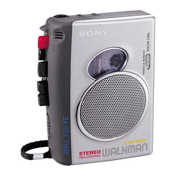
Sony TCS-30D Service Manual
Stereo cassette-corder
Hide thumbs
Also See for TCS-30D:
- Operating instructions (2 pages) ,
- Specifications (2 pages) ,
- Service manual (19 pages)
Table of Contents
Advertisement
Quick Links
SERVICE MANUAL
Ver 1.0 2000. 03
Specifications
Recording system
Tape speed
Frequency range
Speaker
Power output
Input
Output
Variable range of the tape speed
Power requirements
Dimensions (w/h/d) (incl. projecting
parts and controls)
Mass
Supplied accessories
SPECIFICATIONS
4-track 2 channel stereo
4.8 cm/s or 2.4 cm/s
Recording: 250-6,300Hz
Playback: 50-14,000Hz
using nomal (TYPE I) cassette
(with REC TIME switch at
"NORMAL")
7
Approx. 3.6 cm (1
/
in.) dia.
16
350 mW (at 10 % harmonic
distortion)
Microphone input jack (minijack)
sensitivity 0.3 mV for 3 kilo-ohms
or lower impedance microphone
i (headphones) jack (minijack) for
8-300 ohms headphones
From approx. +30% to –15% (with
REC TIME switch at "NORMAL")
3 V DC batteries R6 (AA) × 2/
External DC 3 V power sources
Approx. 91 × 112 × 39.2 mm
× 4
× 1
5
1
9
(3
/
/
/
in.)
8
2
16
Approx. 170 g (6.0 oz.)
Headphones (1)
Stereo microphones (1)
TCS-30D
Canadian Model
Chinese Model
Model Name Using Similar Mechanism
Tape Transport Mechanism Type
Battery life
(Approx. hours) (EIAJ*)
Sony
Sony
alkaline
R6P
LR6 (SG)
(SR)
Playback
9
2
Recording
12
3
* Measured value by the standard of
EIAJ (Electronic Industries
Association of Japan). (Using a Sony
HF series cassette tape)
Note
The battery life may shorten
depending on the operation of the
unit.
Design and specifications are subject
to change without notice.
STEREO CASSETTE-CORDER
US Model
AEP Model
E Model
NEW
MT-30D-118
Advertisement
Table of Contents

Subscribe to Our Youtube Channel
Related Manuals for Sony TCS-30D


Summary of Contents for Sony TCS-30D
- Page 1 Frequency range Recording: 250-6,300Hz * Measured value by the standard of Playback: 50-14,000Hz EIAJ (Electronic Industries using nomal (TYPE I) cassette Association of Japan). (Using a Sony (with REC TIME switch at HF series cassette tape) “NORMAL”) Speaker Note Approx. 3.6 cm (1 in.) dia.
-
Page 2: Table Of Contents
TABLE OF CONTENTS Notes on chip component replacement • Never reuse a disconnected chip component. • Notice that the minus side of a tantalum capacitor may be dam- SERVICING NOTES ..........3 aged by heat. GENERAL ..............4 DISASSEMBLY ............5 MECHANICAL ADJUSTMENTS ....... -
Page 3: Servicing Notes
SECTION 1 SERVICING NOTES THE OPERATION CHECK AND THE VOLTAGE CHECK CHANGE THE SPECIFICATION (US Model Only) WHEN THE MAIN BOARD REMOVED For the mounted MAIN board (A-3021-325-A), the TAP101 and [REC] [PLAY] [FF] [REW] 201 patterns are opened. This set detects which button of , or This specification is for the Canadian, AEP, E, and Chinese mod- was pressed using the POWER switch (S303). -
Page 4: General
SECTION 2 This section is extracted from instruction manual. GENERAL MIC (PLUG IN POWER) x STOP N PLAY SPEED CONTROL m REW/REVIEW M FF/CUE BATT PAUSE . AC power adaptor Adaptador de alimentación de CA Transformador de corrente Erase head Capstan Cabezal de borrado Cabrestante... -
Page 5: Disassembly
SECTION 3 DISASSEMBLY • This set can be disassembled in the order shown below. MAIN BOARD, CABINET (REAR), BELT “LID BLOCK ASSY, CASSETTE” MECHANISM DECK (MT-30D-118) Note: Follow the disassembly procedure in the numerical order given. CABINET (REAR), “LID BLOCK ASSY, CASSETTE” INSTALLATION “SPRING, CASSETTE”... - Page 6 MAIN BOARD, MECHANISM DECK (MT-30D-118) 5 three screws (IB lock) Cabinet (front) 6 claw 7 mechanism deck (MT-30D-118) 1 Remove two solders of electret condenser microphone (MIC901). 1 Remove two solders of motor (M901). 4 MAIN board 1 Remove four solders of 3 screw magnetic head (HRP901).
- Page 7 INSTALLATION MAIN BOARD NOTE: On installation MAIN board, adjust to the S301 and the S303. screw (1.7) screw (M1.4) MAIN board S303 (POWER) S301 (REC/PB) lever (REC) – 7 –...
-
Page 8: Mechanical Adjustments
SECTION 4 MECHANICAL ADJUSTMENTS 1. Clean the following parts with a denatured-alcohol-moistened swab: record/playback head pinch roller erase head rubber belt capstan idlers 2. Demagnetize the record/playback head with a head demagne- tizer. (Do not bring the head demagnetizer close to the erase head) 3. -
Page 9: Electrical Adjustments
SECTION 5 ELECTRICAL ADJUSTMENTS PRECAUTION Tape Speed Adjustment 1. Specified voltage : 2.5 V (DC) Setting: 2. Setting test tape SPEED CONTROL dial : center click WS-48A frequency counter US: 32 Ω (3 kHz, 0 dB) Except US: 16 Ω 0 dB=0.775 V –... -
Page 10: Diagrams
TCS-30D SECTION 6 DIAGRAMS 6-1. BLOCK DIAGRAM • SIGNAL PATH PB PREAMP, MIC AMP, REC AMP HEADPHONES AMP R-CH : PB IC301 RV301 IC302 (1/2) HRP901 (REC/PB) PB IN : REC J301 LINE PB PREAMP OUT A IN A HEADPHONES... -
Page 11: Printed Wiring Boards
TCS-30D 6-2. PRINTED WIRING BOARDS J302 J301 (COMPONENT SIDE) MAIN BOARD (CONDUCTOR SIDE) MAIN BOARD RV301 D401 BATT –2 –1 Q102 S301 (REC/PB) REC C302 –2 –4 C110 C303 MIC901 –1 –3 C210 Q202 C206 C390 C301 R305 C111 R212... -
Page 12: Schematic Diagram
TCS-30D 6-3. SCHEMATIC DIAGRAM • See page 17 for IC Block Diagrams. Note on Schematic Diagram: • Voltages are dc with respect to ground under no-signal • All capacitors are in µF unless otherwise noted. pF: µµF conditions. 50 WV or less are not indicated except for electrolytics no mark : PB and tantalums. -
Page 13: Exploded Views
SECTION 7 EXPLODED VIEWS • IC Block Diagrams NOTE: • -XX and -X mean standardized parts, so they • Items marked “*” are not stocked since they • Abbreviation IC301 CXA2500N-T4 are seldom required for routine service. Some may have some difference from the original 1E: No indication of country of origin one. - Page 14 (2) MECHANISM DECK SECTION-1 (MT-30D-118) HRP901 HE901 M901 supplied Ref. No. Part No. Description Remark Ref. No. Part No. Description Remark X-3377-250-1 LEVER, (2) ASSY, PINCH 3-924-641-01 GEAR (T REEL) 3-925-146-11 BUTTON (FF) (M) 3-924-726-01 SPRING (M GROUND), TORSION 3-925-147-01 BUTTON (REW) (m) 3-907-943-01 BELT (CAPSTAN) 3-925-148-11 BUTTON (PLAY) (N) 3-925-109-01 CUSHION (MOTOR)
- Page 15 (3) MECHANISM DECK SECTION-2 (MT-30D-118) supplied Ref. No. Part No. Description Remark Ref. No. Part No. Description Remark 3-321-483-11 RING, RETAINING (0.25) 3-924-622-01 LEVER (STOP) 3-701-437-51 WASHER 3-045-541-01 SPRING (PR3), TORSION X-3376-786-2 WHEEL ASSY, FLY 3-924-684-01 SPRING (LOCK PLATE), TENSION 3-924-623-01 LEVER (PLAY) 3-924-619-01 LEVER (SW) 3-924-621-01 LEVER (REW)
-
Page 16: Electrical Parts List
SECTION 8 MAIN ELECTRICAL PARTS LIST NOTE: • Due to standardization, replacements in the • Items marked “*” are not stocked since they parts list may be different from the parts speci- are seldom required for routine service. fied in the diagrams or the components used Some delay should be anticipated when order- on the set. - Page 17 MAIN SWITCH Ref. No. Part No. Description Remark Ref. No. Part No. Description Remark < IC > R309 1-216-129-00 METAL CHIP 2.2M 1/10W R310 1-216-049-11 RES-CHIP 1/10W IC301 8-752-089-40 IC CXA2500N-T4 R311 1-216-089-00 RES-CHIP 1/10W IC302 8-759-205-43 IC TA7688F-SO IC303 8-759-650-96 IC BA6640F-E2 R312 1-216-073-00 METAL CHIP...
- Page 18 Ref. No. Part No. Description Remark Ref. No. Part No. Description Remark ACCESSORIES & PACKING MATERIALS ******************************* 1-505-521-11 HEADPHONE (MDR-023) (US) 1-505-855-11 HEADPHONE (MDR-B114) (CND, AEP, E, 1E, CH) 1-542-307-11 MICROPHONE (ECM-J2SL) 3-868-228-11 MANUAL, INSTRUCTION (ENGLISH, SPANISH, PORTUGUESE) (US, AEP, E) 3-868-228-21 MANUAL, INSTRUCTION (ENGLISH, FRENCH, CHINESE) (CND, CH) 3-868-228-31 MANUAL, INSTRUCTION (DUTCH, ITALIAN,...
- Page 19 TCS-30D Sony Corporation 2000C0579-1 9-927-684-11 Personal Audio Division Company Printed in Japan C 2000. 3 – 24 – Published by General Engineering Dept.
Need help?
Do you have a question about the TCS-30D and is the answer not in the manual?
Questions and answers