Table of Contents
Advertisement
SERVICE MANUAL
Manufactured under license from Dolby Laboratories
Licensing Corporation.
"DOLBY" and the double-D symbol a are trademarks
of Dolby Laboratories Licensing Corporation.
MICROFILM
Model Name Using Similar Mechanism
Tape Transport Mechanism Type
SPECIFICATIONS
STEREO CASSETTE DECK
TC-SD1
AEP Model
UK Model
E Model
TC-PX100
TCM-ACLM572
Advertisement
Table of Contents

Related Manuals for Sony TC-SD1


Summary of Contents for Sony TC-SD1
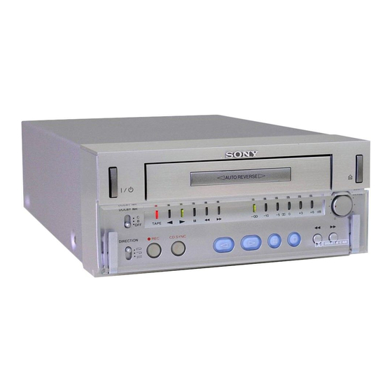
- Page 1 TC-SD1 SERVICE MANUAL AEP Model UK Model E Model Manufactured under license from Dolby Laboratories Model Name Using Similar Mechanism TC-PX100 Licensing Corporation. Tape Transport Mechanism Type TCM-ACLM572 “DOLBY” and the double-D symbol a are trademarks of Dolby Laboratories Licensing Corporation.
-
Page 2: Table Of Contents
COMPONENTS IDENTIFIED BY MARK ! OR DOTTED LINE WITH MARK ! ON THE SCHEMATIC DIAGRAMS AND IN THE PARTS LIST ARE CRITICAL TO SAFE OPERATION. REPLACE THESE COMPONENTS WITH SONY PARTS WHOSE PART NUMBERS APPEAR AS SHOWN IN THIS MANUAL OR IN SUPPLEMENTS PUBLISHED BY SONY. -
Page 3: General
SECTION 1 This section is extracted from instruction manual. GENERAL — 3 —... -
Page 4: Disassembly
SECTION 2 DISASSEMBLY Note : Follow the disassembly procedure in the numerical order given. 2-1. CASE, FRONT PANEL 4 Case 3 Screw (+B 2.6 × 8) 2 Two screws, case stopper 1 Two screws, case stopper 8 Front panel 6 Loading panel Connector M901 7 Two screws... -
Page 5: Mechanism Deck (Tcm-Aclm572)
2-2. MECHANISM DECK (TCM-ACLM572) 4 Connector 5 Mechanism deck (TCM-ACLM572) 2 Connector 3 Connector 1 Four screws (+B 3 × 10) 2-3. CONTROL BOARD, DOLBY BOARD 3 Two screws (+B 2.6 × 8) 1 Two connectors 4 CONTROL board Precaution for assembling : Fix the harness with the clamper. -
Page 6: Power Trans Board, Ac Select Sw Board, Power Board
2-4. POWER TRANS BOARD, AC SELECT SW BOARD, POWER BOARD 3 POWER TRANS board Screw (+B2.6 × 8) 1 Connector 6 Screw (+B2.6 × 8) 8 POWER 2 Two screws board (+PWH3 × 6) 4 Two screws (+B3 × 10) 7 Suport 2-5. -
Page 7: Mechanism Chassis Block
2-6. MECHANISM CHASSIS BLOCK Mechanism chassis Four screws (+P 3 × 6) Screw (+P 3 × 8) 2-7. CAPSTAN REEL MOTOR (M902) Capstan reel motor (M902) Hook the belt. Claws (4 claws) Three screws for motor Remove soldering of the plunger solenoid Plunger solenoid CONTROL board... -
Page 8: Diagrams
SECTION 3 DIAGRAMS 3-1. CIRCUIT BOARDS LOCATION POWER TRANS board CONTROL board REAR PANEL board CONNECTION board POWER board DOLBY board MODE CONTROL board O/C SW board FRONT board VR board — 8 —... -
Page 9: Schematic Diagram - Display Section
TC-SD1 3-2. SCHEMATIC DIAGRAM — DISPLAY SECTION — Note on Schematic Diagram: • All resistors are in Ω and W or less unless otherwise specified. • C : panel designation. Note: The components identified by mark ! or dotted line with mark ! are critical for safety. -
Page 10: Printed Wiring Board — Display Section
TC-SD1 3-3. PRINTED WIRING BOARD — DISPLAY SECTION — • Refer to page 8 for Circuit Boards Location. COMPONENT SIDE CONDUCTOR SIDE • Refer to page 24 for MODE CONTROL board Schematic Diagram. Note on Printed Wiring Board: • Y : parts extracted from the conductor side. -
Page 11: Printed Wiring Board — Main Section
TC-SD1 3-4. PRINTED WIRING BOARD — MAIN SECTION — COMPONENT SIDE • Refer to page 8 for Circuit Boards Location. CONDUCTOR SIDE Note on Printed Wiring Board: • Y : parts extracted from the conductor side. • b : Pattern of the rear side. -
Page 12: Schematic Diagram - Main Section
TC-SD1 3-5. SCHEMATIC DIAGRAM — MAIN SECTION — • Refer to page 25 for IC Block Diagrams. • Refer to page 27 for IC Pin Function Description. • Refer to page 15 for MODE CONTROL board Printed Wiring Board. • Semiconductor Location Ref. -
Page 13: Ic Block Diagrams
3-6. IC BLOCK DIAGRAMS IC02 CXA1561S REC AMP HDET LDET Mode Control HDET LDET IREF REC AMP IC01 µPC4570HA IC03 CXA1598S 19 18 17 16 15 14 13 1 2 3 4 5 6 7 PARA CTRL METER 1 2 3 4 5 6 7 8 9 10 —... - Page 14 IC04 LA5617 CURRENT CURRENT START ON/OFF ON/OFF LIMITER LIMITER CIRCUIT VREF VMUTE OVER HEAT PROTECT VREF ERROR VREF ~ _ 1.8V ERROR IC06 LB1641 T.S.D O.C.P MOTOR MOTOR DRIVE DRIVE FWD/REV/STOP CONTROL LOGIC — 26 —...
-
Page 15: Ic Pin Function Description
3-7. IC PIN FUNCTION DESCRIPTION • CONTROL BOARD IC05 TMP87CH48DF (SYSTEM CONTROL) Pin No. Pin Name Description — System ground terminal OSC-OUT System clock output (8 MHz) OSC-IN System clock input (8 MHz) RESET Reset input — No used — No used TEST Test terminal... - Page 16 Pin No. Pin Name Description PB MUTE Playback mute selector output DOLBY ON/OFF Dolby ON/OFF output DOLBY B/C Dolby B/C output STB-R-LED No used STB-G-LED Power ON LED (green) output PANEL-LED Panel LED (blue) output LEBEL1-LED Level meter 1 (minimum dB) LED (green) output LEVEL2-LED Level meter 2 LED (green) output LEVEL3-LED...
-
Page 17: Mechanical Adjustment
SECTION 4 SECTION 5 MECHANICAL ADJUSTMENT ELECTRICAL ADJUSTMENT Precaution Precaution 1. Clean the following parts with a denatured alcohol-moistened 1. Perform adjusting on the test mode. swab: 2. Demagnetize the record/playback head with a head record/playback heads pinch rollers demagnetizer. erase head rubber belts 3. - Page 18 Record/Playback Head Azimuth Adjustment 4. Enter the FWD mode and perform steps 1 to 3. 5. Check that the phase difference between L-CH and R-CH is in Note: • Perform this adjustment after the head is turned around. the range of in-phase to 90°. (If the head is positioned in the FWD direction, turn around 6.
- Page 19 Playback Level Adjustment Record Level Adjustment Procedure : Setting : • The REC LEVEL control must be positioned at the standard record 1. Mode : FWD playback level position. (Refer to page 29.) test tape Procedure : P-4-L300 1. Record (315Hz, 0dB) level meter AF OSC...
- Page 20 Adjustment Location: DOLBY board (Component Side) SFR12 SFR03 SFR01 SFR11 SFR04 IC02 SFR02 IC03 IC01 CONTROL board (Component Side) CN13 IC05 — 32 —...
-
Page 21: Exploded Views
Description Remarks 3-033-056-01 WINDOW, GLASS * 16 A-2007-825-A CONNECTION BOARD, COMPLETE 4-212-579-11 BRACKET (GLASS) 3-033-080-01 DOLBY KNOB 4-942-636-21 EMBLEM (NO.3.5), SONY 3-033-078-01 DIRECTION KNOB 4-214-458-01 TAPE 4-212-557-01 BUTTON (REC) 3-033-074-01 CHASSIS, FRONT 3-033-075-01 LENS 3-033-079-01 REC LEVEL KNOB * 21... -
Page 22: Chassis Section
6-2. CHASSIS SECTION not supplied TCM-ACLM572 not supplied not supplied Ref. No. Part No. Description Remarks Ref. No. Part No. Description Remarks 3-033-060-01 SPRING, PLATE * 59 A-2007-820-A POWER BOARD, COMPLETE 4-213-692-02 TAPE (SPRING) * 60 1-672-764-11 POWER TRANS BOARD X-4950-381-1 BRACKET (R) ASSY * 61 3-035-607-01 REAR PANEL (AEP, UK) -
Page 23: Mechanism Deck Section-1 (Tcm-Aclm572)
6-3. MECHANISM DECK SECTION-1 (TCM-ACLM572) M901 S901 S902 Ref. No. Part No. Description Remarks Ref. No. Part No. Description Remarks 3-017-214-01 HOLDER 3-017-234-01 GROUND, PLATE 3-017-215-01 ARM (A) 3-017-243-01 NUT 3-017-233-01 RACK, GEAR 3-017-242-01 BUFFER 3-017-216-01 ARM (C) 3-017-232-01 GEAR (B) 3-017-241-01 SCREW (1.6 ×... -
Page 24: Mechanism Deck Section-2 (Tcm-Aclm572)
6-4. MECHANISM DECK SECTION-2 (TCM-ACLM572) HRPE901 M902 supplied not supplied supplied not supplied Ref. No. Part No. Description Remarks Ref. No. Part No. Description Remarks 3-017-294-01 SCREW (S), SPECIAL 3-017-300-01 WASHER, FLAT 3-017-273-01 LEVER (AC), SPRING 3-017-255-01 PINCH ROLLER (R) 3-017-270-01 AC, LEVER 3-017-296-01 CUSHION (MOTOR) 3-017-279-01 SCREW (M2), SPECIAL... -
Page 25: Mechanism Deck Section-3 (Tcm-Aclm572)
6-5. MECHANISM DECK SECTION-3 (TCM-ACLM572) Ref. No. Part No. Description Remarks Ref. No. Part No. Description Remarks 3-017-258-01 FLYWHEEL (R) 3-017-262-01 REEL, BUSHING 3-017-257-01 FLYWHEEL (F) 3-017-272-01 SPRING (BT) 3-017-284-01 BELT (SUB) 3-017-281-01 WASHER, FLAT 3-017-265-01 IDLER, GEAR 3-017-256-01 ARM (PLAY) 3-017-305-01 GEAR (P) 3-017-275-01 LOCK, SPRING CAM 3-017-283-01 WASHER, FLAT... -
Page 26: Electrical Parts List
CONNECTION SECTION 7 ELECTRICAL PARTS LIST CONTROL NOTE: • Due to standardization, replacements in the • CAPACITORS: • SEMICONDUCTORS parts list may be different from the parts uF: µF In each case, u: µ, for example: specified in the diagrams or the components •... - Page 27 CONTROL DOLBY Ref. No. Part No. Description Remarks Ref. No. Part No. Description Remarks < RESISTOR > A-2007-818-A DOLBY BOARD, COMPLETE ********************** 1-249-437-11 CARBON 1/4W 1-249-427-11 CARBON 6.8K 1/4W F < CAPACITOR > 1-247-843-11 CARBON 3.3K 1/4W 1-247-879-11 CARBON 100K 1/4W 1-162-292-31 CERAMIC 680PF...
- Page 28 DOLBY Ref. No. Part No. Description Remarks Ref. No. Part No. Description Remarks < CONNECTOR > 1-247-855-11 CARBON 1/4W 1-247-855-11 CARBON 1/4W * CN01 1-564-707-11 PIN, CONNECTOR (SMALL TYPE) 5P 1-247-843-11 CARBON 3.3K 1/4W CN04 1-785-778-11 SOCKET, CONNECTOR 8P 1-247-843-11 CARBON 3.3K 1/4W 1-249-431-11 CARBON...
- Page 29 DOLBY FRONT MODE CONTROL Ref. No. Part No. Description Remarks Ref. No. Part No. Description Remarks R016 1-249-409-11 CARBON 1/4W F < RESISTOR > R19A 1-249-390-11 CARBON 1/4W F R40A 1-247-847-11 CARBON 4.7K 1/4W R215 1-247-827-11 CARBON 1/4W R400 1-247-903-00 CARBON 1/4W R216 1-249-417-11 CARBON...
- Page 30 O/C SW PANEL SW POWER POWER TRANS Ref. No. Part No. Description Remarks Ref. No. Part No. Description Remarks A-2007-823-A O/C SW BOARD, COMPLETE < IC > *********************** IC04 8-759-288-53 IC LA5617 < SWITCH > IC10 8-759-604-35 IC M5F78M05L IC11 8-759-549-81 IC P82B715TD.112 1-572-647-11 SWITCH, KEY BOARD (EJECT) <...
- Page 31 Ref. No. Part No. Description Remarks Ref. No. Part No. Description Remarks 1-672-765-11 VR BOARD ************** HARDWARE LIST ********* ************** < VARIABLE RESISTOR > 7-685-534-19 SCREW +B 2.6 × 8 (TYPE2) 7-685-533-19 SCREW +B 2.6 × 6 (TYPE2) VR02 1-225-749-11 RES, VAR, CARBON 50K/50K (REC LEVEL) 7-685-535-19 SCREW +B 2.6 ×...
- Page 32 TC-SD1 Sony Corporation 99A1653-1 Printed in Japan ©1999.1 Home A&V Products Company 9-922-983-11 Published by Quality Assurance Dept. — 44 — (Shinagawa)
Need help?
Do you have a question about the TC-SD1 and is the answer not in the manual?
Questions and answers