Table of Contents

Related Manuals for Observator Instruments ANALITE NEP-695


Summary of Contents for Observator Instruments ANALITE NEP-695
- Page 1 Manual NEP-695 Long-life logging probe Version: 20221009 Status: Final Confidentiality: Not confidential Date: 09 October 2022 Author: Vic Grosjean www.observator.com Manual | NEP-695 Page 1 | 51 Status: Final | Not confidential V20221009...
- Page 2 Document history The Observator range is in continuous development and so specifications may be subject to change without prior notice. When in doubt about the accuracy of this document, contact the Observator Group. NEP-695 Reference documents Type of document / tool Product type and name (incl.
- Page 3 Revision history Date Amendments Company, position 2019-06-19 Initial document creation Observator Australia, Document Controller 2019-07-26 Add charging information Observator Australia, Document Controller 2019-08-19 Completed NEP-695 manual Observator Australia, Document Controller 2019-08-20 Quality review Observator Australia, Operation Manager 2019-08-30 Edited packing list Observator Australia, Document Controller 2020-01-30...
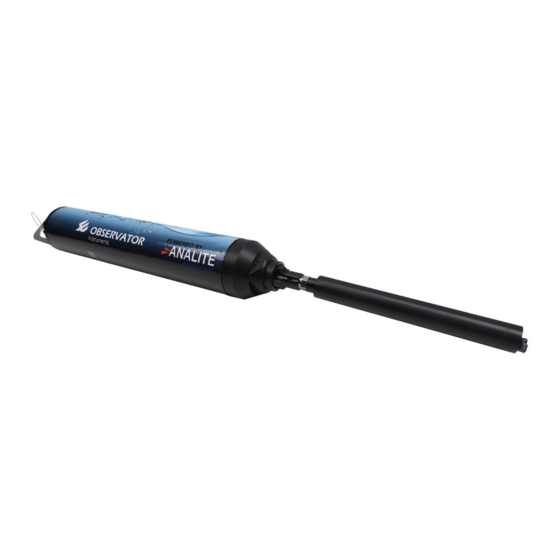
- Page 4 Summary Thank you for purchasing the new Analite NEP-695 long-life logging probe. It will give you years of service if you install and maintain the probe according to guidelines set out in this manual. The NEP-695 is an all-in-one device that contains a scriptable Serial Digital Interface SDI-12 logger with an integrated rechargeable battery designed for long-term operations.
-
Page 5: Table Of Contents
Table of contents Applications ........................7 Safety ..........................8 Specification ........................9 What you will find in the box ..................11 Accessories ........................13 Mechanical installation ....................16 Connect NEP-695 to a single NEP-5000 ..................16 NEP-695 Multiple sensor configurations ................... 17 Mounting NEP-695 into a data buoy ....................18 Power NEP-695 using a solar panel for long-term deployment ............ - Page 6 11.4 Power estimation ..........................48 11.5 Example code ............................ 49 Appendix D: How to configure other SDI-12 sensors ..........50 Manual | NEP-695 Page 6 | 51 Status: Final | Not confidential V20221009...
-
Page 7: Applications
Applications The NEP-695 products are ideal for water quality, food processing, waste treatment, and environmental compliance for dredging operations. They are also an ideal dropping solution for data-buoys and river monitoring applications. Typical use includes applications such as: 1. Monitoring of streams and rivers 2. -
Page 8: Safety
Safety Please check with your supplier or material specifications before using the sensor in an unknown chemical. Always use the charger provided to power the probe. Do not intend to use the NEP-695 with logging probes that are not approved by your supplier. -
Page 9: Specification
Specification Dimensions Length 541.6mm Diameter 88.9mm Mechanical 2.4kg – including batteries Weight Manual | NEP-695 Page 9 | 51 Status: Final | Not confidential V20221009... - Page 10 Specifications Operating temperature -5°C (non-freezing) to 50°C Storage temperature -10°C to 55°C Construction Outer tube construction with polycarbonate tube with a structural support built using a stainless- steel chassis. The probe interface assembly and rear electrical interface assembly is built using machine Delrin plastic.
-
Page 11: What You Will Find In The Box
What you will find in the box When the product is delivered, this is what you will find in the box: Items found in the box NEP-695 logging probe NEP-695 Turbidity & temperature long-life logging probe with loaded script. DC charging adapter NEP-695-charge Charger adapter for NEP-695, including the adaptor for the purchased country. - Page 12 Items found in the box NEP-5000 Probe NEP-5000 NEP-CBL - Probe cable in meters. Blue box calibration module and USB cable* Module and PC configuration and calibration software. NEP-CFG (*) on your first NEP-5000 order only. SubConn female pigtail** NEP-CFG-SF (**) Only included in the shipment when the NEP-5000 has a male SubConn connector.
-
Page 13: Accessories
Accessories Observator Instruments offers a wide range of accessories for NEP-5000 & NEP-695. The range of products are directly available from the website: Accessories Case NEP-CASE Wiper replacement kit NEP-WIPER-KIT - comprising of 4 silicon wipers and a hex fastening key. - Page 14 Accessories Calibration kit for SubConn probes** NEP-CFG-SF - comprising of a blue box calibration module, USB cable and a SubConn female pigtail. (**) Only for NEP-5000 with male SubConn connector. Wiring is different for SDI-12 and RS422/RS485. Calibration solutions NEP-CAL-GSF Brown bottle for calibration NEP-CAL-BTL NEP-5000 connection cable...
- Page 15 O-ring replacement kit for NEP-695 NEP-695-ORI Spare battery for NEP-695 NEP-695-BAT Note: Additional customised accessories are also available for long-term deployment or multiple sensor configuration such as: Photovoltaic (PV) panel, long-deployment protective cap. Manual | NEP-695 Page 15 | 51 Status: Final | Not confidential V20221009...
-
Page 16: Mechanical Installation
Mechanical installation 6.1 Connect NEP-695 to a single NEP-5000 The following section describes how to connect a single NEP-5000 sensor to the NEP-695 logging probe. Please proceed as follows in order to avoid damaging the NEP-695 connector: • Firmly hold the NEP-5000 probe. Adjust the NEP-5000 male connector to fit the female NEP-695 connector. -
Page 17: Nep-695 Multiple Sensor Configurations
6.2 NEP-695 Multiple sensor configurations Users may apply the following configuration diagram to power multiple NEP-5000 sensors (up to 9 sensors in parallel): Figure 6.B: Connect NEP-695 to multiple NEP-5000 Note: Please contact your sensor manufacturer to request our special made cables for multiple sensor configuration. -
Page 18: Mounting Nep-695 Into A Data Buoy
Do not use cable clamps. Do not crush the body of the sensor. Attachment point Note: A range of data-buoys fitting NEP-695 logging applications are available from the manufacturer. Please contact Observator Instruments for more information. Manual | NEP-695 Page 18 | 51 Status: Final | Not confidential... -
Page 19: Power Nep-695 Using A Solar Panel For Long-Term Deployment
Users may apply the following power diagram to power the NEP-695 using a PV panel for long-term usage or remote deployment: Figure 6.C: Power NEP-695 using a solar panel Note: Additional customised accessories are available from Observator Instruments for long-term usage such as PV panels and long-deployment protective caps. Manual | NEP-695... -
Page 20: Charging & Maintenance
Charging & maintenance 7.1 Charge NEP-695 Follow these instructions to charge the NEP-695 logging probe: 1. To avoid any risk of water ingress falling onto the electronics, flip the probe up-side down, hold the main body of the probe tight and unscrew the control lid off (make sure to let the water evacuate and dry the lid completely). -
Page 21: Change Nep-695 Battery
4. Remove the charging cable and place the protective cap back onto the probe. Firmly press down to engage the O-ring (and ensure the sealing). Once engaged, screw the cap by slowly turning clockwise until the cap is fully screwed on. Firmly press the Turn the cap cap downwards... - Page 22 Flip the probe straight, and manually switch off the probe (the LED will no-longer be flashing). Partially place the control lid back on (you only need to screw a few threads for the lid to hold in place). Hold the main body of the probe tight and unscrew the battery lid off (be gentle and do not pull too much on the battery cables).
- Page 23 Flip the probe up-side down, and partially lift the orange tape just enough to see where the battery is connected. Press on the battery connector pin (use a tool or nails as necessary) while pulling the connector off at the same time. Lift the battery all the way and remove the battery.
- Page 24 To install the new battery, make sure the male connector faces the connector head before placing the battery into the probe (the battery should be placed exactly with the same orientation as before and it should fully align with the cable). Partially hold the battery using the orange tape just enough to connect the battery connector.
- Page 25 Lower down the battery and tidy up the 2 cables (gently press the cables in each corner, the cables should lie flat with the other cables). Screw the battery lid on until it is tight. Always visually make sure there is no gap left. Manual | NEP-695 Page 25 | 51 Status: Final | Not confidential...
-
Page 26: Led Indicators
Flip the probe straight, unscrew the control lid and manually switch on the probe. Screw the control lid onto the probe until it is tight. Always visually make sure there is no gap left. Check the LED status, if the red LED is flashing on every 10 seconds, it means that the probe is logging. -
Page 27: Maintenance & Storage
7.4 Maintenance & storage It is strongly recommended that the logging probe be thoroughly washed in clean water after deployment and prior to storage. In the field, wash the probe with fresh water and clean it with a soft cloth. In the office, we recommend to clean the sensor with fresh water and dry the sensor with compressed air. -
Page 28: Software Installation
Software installation 8.1 Download & install PC200W software 1. Register an account onto “Campbell Scientific website”. 2. Go to the “PC200W download page” and download the software. 3. To avoid any risk of water ingress falling onto the electronics, flip the probe up-side down, hold the main body of the probe tight and unscrew the control lid off (make sure to let the water evacuate and dry the lid completely). - Page 29 5. Run the software on to your Windows machine and select “Next”. 6. Select “CR300Series” data logger and select “Next”. 7. Open the “Windows device manager” from your control panel, find the newly connected device and identify the Communication port (COM port) number. Manual | NEP-695 Page 29 | 51 Status: Final | Not confidential...
- Page 30 The driver is not installed Figure 8.A: Device manager window Select “CR300” COM port and select “Next”. Note: User may be required to select “Install USB Driver” prior to selecting the correct port. Manual | NEP-695 Page 30 | 51 Status: Final | Not confidential V20221009...
- Page 31 8. Select “115200” baud rate and select “Next”. 9. Select “0” security code and select “Next”. Manual | NEP-695 Page 31 | 51 Status: Final | Not confidential V20221009...
- Page 32 10. Select “Next”. 11. Select “Yes” to test the communication and select “Next” a few times. 12. Setup the clock and select “Next” a few times or “Finish”. Manual | NEP-695 Page 32 | 51 Status: Final | Not confidential V20221009...
- Page 33 13. When finished, select disconnect on the Personal Computer (PC) configuration software. 14. Disconnect the Micro-USB cable from your computer and from the NEP-695 probe and place the protective cap back onto the probe. Firmly press down to engage the O-ring (and ensure the sealing). Once engaged, screw the cap by slowly turning clockwise until the cap is fully screwed on.
-
Page 34: Retrieve The Collected Data
8.2 Retrieve the collected data 1. Connect the NEP-695 to your computer (refer to section 8.1 “Download & install PC200W software”, steps 3 & 4). 2. Open PC200W software and select connect. 3. Select the “Monitor Data” tab to observe the temperature and turbidity value in real time. Note 1: User can “Add”... - Page 35 4. To start downloading data, select the “Collect data” tab. 5. Select “New data from data logger”, then double click on the table. Manual | NEP-695 Page 35 | 51 Status: Final | Not confidential V20221009...
- Page 36 6. Select the table you wish to extract and select “OK”. 7. Select the file output format type (e.g. *.csv), select the location, and click “Save”. Note: By default, the file format is set to “.dat”. Manual | NEP-695 Page 36 | 51 Status: Final | Not confidential V20221009...
- Page 37 8. Finally click on “Start data collection” (to actually save the file), and select “OK”. 9. When finished, select “Disconnect” on the PC configuration software. Manual | NEP-695 Page 37 | 51 Status: Final | Not confidential V20221009...
-
Page 38: Clear Up The Memory
8.3 Clear up the memory Before a new deployment, users may wish to clear the memory on the NEP-695 probe as follows: 1. In the menu, select “Data logger” and “File Control…”. 2. Select the file you wish to be removed and click “Delete”. Note: User may also select the “Format”... -
Page 39: Getting Started With Scripting
8.4 Getting started with scripting The NEP-695 comes with a pre-loaded built-in script (default script) which can be used to operate with NEP-5000 sensors. Please refer to section 9, “Appendix A: Default script for single turbidity measurement with optical wiping” to access the default script for single turbidity measurement with optical wiping section for more information. - Page 40 3. Select “Yes”, then, select your script file. Note: Examples of script files are available in the appendixes of this manual. Manual | NEP-695 Page 40 | 51 Status: Final | Not confidential V20221009...
-
Page 41: Appendix A: Default Script For Single Turbidity Measurement With Optical Wiping
Appendix A: Default script for single turbidity measurement with optical wiping 9.1 Script objectives The default script is pre-loaded onto all NEP-695 logging probes (unless otherwise requested). The script turns on the sensor. After the warm up time elapses, it performs an optical wiping followed by a single turbidity measurement and stores data at each scan (every minutes). -
Page 42: Flow Chart
Must include: • SDI-12 data accusation time = 10s • SDI-12 address = 0 • Power on wipe off 9.3 Flow chart 9.4 Power estimation The following table represents the power estimation for turbidity in auto-range (ten seconds) with optical wipe. -
Page 43: Example Code
Note: All of the above estimations are calculated for ideal temperatures of 25°C. Battery aging and self-discharge are not considered. When deploying for more than three months, the estimation can vary by approximately 30%. 9.5 Example code The following script can be adapted to perform similar operations (e.g. change scanning intervals, add data storing tables, change units, etc…). -
Page 44: Appendix B: Single Turbidity Measurement And Built-In Temperature Measurement With Optical Wiping
10 Appendix B: Single turbidity measurement and built-in temperature measurement with optical wiping 10.1 Script objectives This script can be loaded onto all NEP-695 logging probes using the CR-300 PW200 application. The script turns on the sensor. After the warm up time elapses, it performs an optical wiping followed by a single turbidity measurement, a temperature measurement and stores data at each scan (every 5 minutes). -
Page 45: Flow Chart
Must include: • SDI-12 data accusation time = 10s • SDI-12 address = 0 • Power on wipe off • Auto range selected 10.3 Flow chart 10.4 Power estimation The following table represents the power estimation for turbidity in auto-range (ten seconds) with optical wipe and temperature measurement. -
Page 46: Example Code
Note: All of the above estimations are calculated for ideal temperatures of 25°C. Battery aging and self-discharge are not considered. When deploying for more than ten months, the estimation can vary by approximately 30%. 10.5 Example code The following script can be adapted to perform similar operations (e.g. change scanning intervals, add data storing tables, change units, etc…). -
Page 47: Appendix C: Multiple Turbidity Measurements In Statistical Analysis With Optical Wiping
11 Appendix C: Multiple turbidity measurements in statistical analysis with optical wiping 11.1 Script objectives This script can be loaded onto all NEP-695 logging probes using the CR-300 PW200 application. The script turns on the sensor. After the warm up time elapses, it performs an optical wiping followed by multiple turbidity measurements and stores data at each scan (every five minutes). -
Page 48: Flow Chart
Must include: • SDI-12 data accusation time = 10s • SDI-12 address = 0 • Power on wipe off • Auto range selected. 11.3 Flow chart 11.4 Power estimation The following table represents the power estimation for turbidity in auto-range (fifty seconds) statistical mode (five samples) with optical wipe and temperature measurement. - Page 49 11.5 Example code The following script can be adapted to perform similar operations (e.g. change scanning intervals, add data storing tables, change units, etc…). 'CR300 Series 'Declare Variables and Units Public BattV Public PTemp_C Public SDI12_1(1) Public SDI12_2(6) Alias SDI12_1(1)=Wipe_stats Alias SDI12_2(1)=Turbidity Alias SDI12_2(2)=...
- Page 50 12 Appendix D: How to configure other SDI-12 sensors The NEP-695 is compatible with other SDI-12 sensors. Custom scripts and instructions are available to help you configure other SDI-12 sensors. Please contact Observator Instruments for further recommendations based on your sensor configuration.
-
Page 51: Manual | Nep-695 Page 5
© Copyright – Observator Group Since 1924 Observator has evolved to be a trend-setting developer and supplier in a wide variety of industries. Originating from the Netherlands, Observator has grown into an internationally oriented company with a worldwide distribution network and offices in Australia, Germany, the Netherlands, Singapore and the United Kingdom.
Need help?
Do you have a question about the ANALITE NEP-695 and is the answer not in the manual?
Questions and answers