Table of Contents
Advertisement
Quick Links
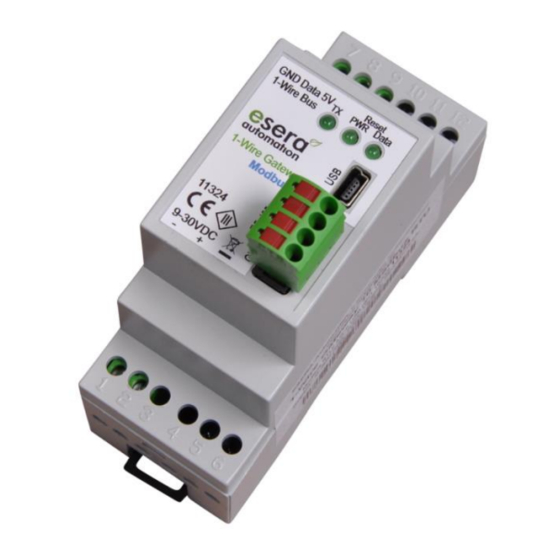
Art. No. 11324
1-Wire Gateway for autonomous communication between
PLC and a 1-Wire sensor and actuator network
Fast readout of all 1-Wire devices in the
1-2 seconds clock
Data output via Modbus RTU (RS485) Protocol
Processed sensor and actuator data
Status of each sensor and actuator can be called up
Convenient configuration program
No additional drivers necessary
Optional data storage in case of interruption of
Communication to the control system / host system
Power supply for 1-Wire network
Designed for all 1-Wire network sizes
DIN rail enclosure for switchboard assembly
Wide supply voltage range
Management of all ESERA automation and many
Standard 1-Wire sensors and actuators
1
Introduction
Before you begin with the installation of the 1-Wire Gateway 10 Modbus and put the device into operation,
please read these operating instructions carefully until the end, especially the section on safety instructions.
All settings and configurations of the 1-Wire Gateway are carried out with the ESERA Config Tool 3. You can
find this software on the ESERA website. Please observe the operating instructions for the
ESERA Config Tool 3, which can be found within the Config Tool 3 software under the "HELP/SUPPORT"
tab.
2
Product description
Standard Modbus RTU Protocol
You can communicate with your industrial controller, e.g. PLC, via standard Modbus RTU protocol with the 1-
Wire Gateway 10. The addressing is clearly structured, comparable to many other Modbus systems.
Addresses for system, sensor and actuator data are available.
We provide an address overview with all available data points via the download area of the article on our
website and via the ESERA Config Tool 3 configuration software.
3
Auto-E-Connect® Support
The ESERA Auto-E-Connect® 1-Wire Plug and Play system will be used for the
1-Wire Bus supported. This enables fully automatic configurations of 1-Wire sensors
and actuators on the 1-Wire bus. It is optimized for industrial applications and
enables significant added value beyond the sensor and chip data.
The Auto-E-Connect function automatically recognizes ESERA chips, sensors and actuators, starts suitable
libraries and outputs fully formatted data.
The Auto-E-Connect functionality will be available from mid 2020 via 1-Wire Controllers, 1-Wire Gateways and
1-Wire ECO from ESERA available.
Further information on ESERA Auto-E-Connect can be found on the ESERA website, ESERA Config-Tool 3, or in
the download area for this article in the ESERA Webshop.
All rights reserved. Reproduction as well as electronic duplication of this user guide, complete or in part, requires the written consent of
ESERA GmbH. Errors and technical modification subject to change. ESERA GmbH, ESERA-Automation 2020
www.esera.de
User Guide
1-Wire Gateway 10 Modbus RTU
11324 V2.0 R1.0 Manual
Page 1 of 8
Advertisement
Table of Contents

Related Manuals for esera automation auto connect 11324


Summary of Contents for esera automation auto connect 11324
- Page 1 Designed for all 1-Wire network sizes DIN rail enclosure for switchboard assembly Wide supply voltage range Management of all ESERA automation and many Standard 1-Wire sensors and actuators Introduction Before you begin with the installation of the 1-Wire Gateway 10 Modbus and put the device into operation, please read these operating instructions carefully until the end, especially the section on safety instructions.
- Page 2 Equipment Standalone Controller The 1-Wire Gateway is designed for autonomous management of a 1-Wire network. You no longer need to worry about 1-Wire commands or formulas to evaluate the sensor data. The 1-Wire Gateway 10 automatically scans the 1-Wire network for new sensors and actuators and provides the corresponding data in plain text using the Modbus protocol, depending on the modules found.
- Page 3 Art. No. 11324 Environmental conditions Temperature, operation -10°C to +55°C (extended temperature range possible on request) Humidity: 10 - 92% (non-condensing) Protection system: IP20 Protection class: Dimensions: 35 x 90 x 70mm (WxHxD) Conformity EN 50090-2-2 EN, 61000-4-2 ESD, EN 61000-4-3 HF, EN 61000-4-4 Burst, EN 61000-4-5 Surge, EN 61000-6-1 Störfestigkeit, EN 61000-6-3 Störstrahlungen, RoHS The module has different display LED´s.
- Page 4 Firmware-Update A firmware update can be performed with the ESERA Config Tool 3 software under the "DEBUG/DATA" tab via the USB interface. The "DOWNLOAD FIRMWARE" button opens a window for downloading new software (firmware) for the 1-Wire Controller / 1-Wire Gateway.
- Page 5 Art. No. 11324 Connection example 1-Wire Gateway 10, 1-Wire Hub III, sensors and actuators www.esera.de All rights reserved. Reproduction as well as electronic duplication of this user guide, complete or in part, requires the written consent of ESERA GmbH. Errors and technical modification subject to change. ESERA GmbH, ESERA-Automation 2020 www.esera.de 11324 V2.0 R1.0 Manual Page 5 of 8...
- Page 6 Software Data interface Modbus RTU and ESERA ASCII text protocol The Ethernet interface can be configured using the Windows ESERA program Config Tool 3. This program can be found in the download area of the ESERA online shop. 14.1 Configuration and Communication with 1-Wire Gateway 10 The 1-Wire Gateway 10 has extensive configuration and formatting options, which can be read out and operated with the ESERA Config Tool 3.
- Page 7 Art. No. 11324 Operating conditions The assembly may only be operated at the specified voltages and ambient conditions. The device can be operated in any position. The device is intended for use in dry and dust-free rooms. If condensation is formed, allow at least 2 hours for the unit to acclimatize. The assembly can only be put into operation under the supervision of a qualified electrician.
- Page 8 Warranty ESERA GmbH guarantees that the sold goods are free of material and manufacturing defects at the time of transfer of risk and have the contractually assured properties. The statutory warranty period of two years from invoicing shall apply. The warranty does not cover normal wear and tear.
Need help?
Do you have a question about the auto connect 11324 and is the answer not in the manual?
Questions and answers