Table of Contents
Advertisement
Quick Links
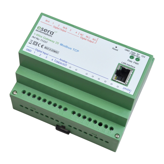
Art. No. 11337
1-Wire Gateway for self-communication
between PLC and a 1-Wire sensor and
actuator Network
Data evaluation of all 1-Wire modules in 1 - 2
seconds increments
Modbus data output as TCP protocol
Edited sensor- and actuator data
Status updates for all sensors and actuators
Easy configuration
No extra drivers needed
Data storage in case of loss of communication
to the host system (optional)
Power supply for 1-Wire network
Designed for all dimensions of 1-Wire
networks
DIN rail housing for switchboard assembly
Wide range of power voltage
Management of all ESERA-Automation 1-Wire
modules and many of standard 1-Wire
sensors and actuators (e.g. switch-modules)
1
Introduction
Before you start assembling the 1-Wire Gateway 20 Modbus TCP and before you take the device into
operation, please read this assembly and operating instruction carefully to the end, especially the section
referring to the safety notes.
We recommend to use Config-Tool 3 for all kind of setup and configuration tasks. Please find the latest
release on our website at, www.esera.de. Please also refer to the Help/Support section to find the user guide
for Config-Tool 3.
2
Product description
Standard Modbus TCP protocol
You can use your industrial controller, e.g. PLC and standard TCP protocol to connect to the 1-Wire
Gateway 20. Addressing is similar to other Modbus systems and easy to handle. You can use addresses
for system data, sensor data and actuator devices. A complete address list including all available data
points is available for
download
ESERA configuration software Config-Tool 3.
Standalone controller
The 1-Wire Gateway 20 Modbus is designed to control 1-Wire Networks. You no longer have to worry
about 1-Wire commands or algorithms to analyze sensor data. 1-Wire Gateway 20 Modbus scans 1-Wire
Networks by itself in order to identify new sensors or actuator devices. All data found were automatically
provided in a ready to use Modbus protocol format.
All rights reserved. Reproduction as well as electronic duplication of this user guide, complete or in part, requires the written consent of
ESERA GmbH. Errors and technical modification subject to change. ESERA GmbH, ESERA-Automation 2020
www.esera.de
User Guide
1-Wire Gateway 20 Modbus TCP
on our webpage. These addresses are also available within the
11337 V2.0 R1.0 Manual
Page 1 of 10
Advertisement
Table of Contents

Subscribe to Our Youtube Channel
Related Manuals for esera automation 1-Wire Gateway 20 Modbus TCP


Summary of Contents for esera automation 1-Wire Gateway 20 Modbus TCP
- Page 1 (e.g. switch-modules) Introduction Before you start assembling the 1-Wire Gateway 20 Modbus TCP and before you take the device into operation, please read this assembly and operating instruction carefully to the end, especially the section referring to the safety notes.
- Page 2 Formatted data output 1-Wire Gateway 20 Modbus provides plausibility checked sensor and actuator data in a ready to use format. E.g. temperature sensor provides values in Celsius degrees with 2 decimal places. You only need to divide this number by 100. Within the 1-Wire Gateway a product specific transformation table is available for most of our selling 1-Wire sensor and actuator products.
-
Page 3: Ambient Conditions
Art. No. 11337 Ambient conditions Temperature, operation -10 °C up to +55 °C (extended temperature range available upon request) 10 – 92 % (non-condensing) Air humidity: Protection system: IP20 Protection class: Dimensions: 35 x 90 x 70mm (WxHxD) Conformity EN 50090-2-2 EN 61000-4-2, ESD EN 61000-4-3, HF EN 61000-4-4, Burst... - Page 4 Connection All rights reserved. Reproduction as well as electronic duplication of this user guide, complete or in part, requires the written consent of ESERA GmbH. Errors and technical modification subject to change. ESERA GmbH, ESERA-Automation 2020 www.esera.de 11337 V2.0 R1.0 Manual Page 4 of 10...
- Page 5 Art. No. 11337 Module bottom side (power supply, digital input and analog output) 1 = GND/negative digital input isolated to negative supply 2 = digital input 1 10 – 30 VDC 3 = digital input 2 10 – 30 VDC 4 = digital input 3 10 –...
- Page 6 Connection - Example 1-Wire Gateway, sensors and actuators www.esera.de All rights reserved. Reproduction as well as electronic duplication of this user guide, complete or in part, requires the written consent of ESERA GmbH. Errors and technical modification subject to change. ESERA GmbH, ESERA-Automation 2020 www.esera.de 11337 V2.0 R1.0 Manual Page 6 of 10...
- Page 7 Art. No. 11337 Data interface Modbus TCP and ESERA ASCII text protocol The Ethernet interface is configured using the Windows ESERA program "Config-Tool 3". You can find this program in the download area of the ESERA online shop. Integration in IP-Symcon / ESERA-Station ESERA IP-Symcon software modules are provided at our webpage for easy integration of the 4-fold analog input in IP-Symcon by using a 1-Wire Controller / 1-Wire Gateway.
-
Page 8: Modbus Tcp Protocol
Recovery function Firmware-update Should an error occur during the firmware update e.g. losing power while updating the firmware, a recovery function can be started. Press and hold the reset button (the reset button is located beneath hole no. 30 at module top side). Then start the update in Config- Tool 3 and release the reset button after 1 second after the update has been started. -
Page 9: Operating Conditions
Art. No. 11337 Operating conditions The operation of the assembly group can take place only on condition of observing the required voltage and the ambient conditions. The operating position of the device is irrelevant. The device is meant to be used in dry and dust-free areas. -
Page 10: Warranty
Commissioning may only be realized if the circuit is built into a contact proof housing. If measurements with an open housing are unavoidable, for safety reasons an isolating transformer must be installed upstream or a suitable power supply can be used. ...
Need help?
Do you have a question about the 1-Wire Gateway 20 Modbus TCP and is the answer not in the manual?
Questions and answers