Advertisement
Quick Links
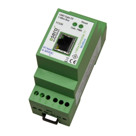
Art. No. 11336
1-Wire Gateway for autonomous communication between
PLC and a 1-Wire Sensor and Actuator network
Data evaluation of all 1-Wire modules in 2 seconds
increments
Modbus data output as TCP protocol
Processed sensor- and actuator data
Status of each sensor and actuator can be called up
Easy configuration
No extra drivers needed
Data storage in case of loss of communication to the host
system (optional)
Power supply for 1-Wire network
Designed for all dimensions of 1-Wire networks
DIN rail enclosure for switchboard assembly
Wide range of power voltage
Management of all ESERA-Automation 1-Wire modules and
many of standard 1-Wire sensors and actuators (switch-
module)
1
Introduction
Before you start assembling the 1-Wire Gateway 11 Modbus TCP and before you take the device into operation,
please read this assembly and operating instruction carefully to the end, especially the section referring to the
safety notes.
We recommend to use Config-Tool 3 for all kind of setup and configuration tasks. Please find the latest release
on our website at, www.esera.de. Please also refer to the Help/Support section to find the user guide for Config-
Tool 3.
2
Product description
Standard Modbus TCP protocol
You can use your industrial controller, e.g. SPS and standard TCP protocol to connect to the 1-Wire
Gateway 11. Addressing is similar to other Modbus systems and easy to handle. You can use addresses for
system data, sensor data and actuator devices. A complete address list including all available data points is
available for
download
on our webpage. These addresses are also available within the ESERA configuration
software Config-Tool 3.
3
Auto-E-Connect® Support
The ESERA Auto-E-Connect® 1-Wire Plug and Play system will be used for the
1-Wire Bus supported. This enables fully automatic configurations of 1-Wire sensors
and actuators on the 1-Wire bus. It is optimized for industrial applications and
enables significant added value beyond the sensor and chip data.
The Auto-E-Connect function automatically recognizes ESERA chips, sensors and actuators, starts suitable
libraries and outputs fully formatted data.
All rights reserved. Reproduction as well as electronic duplication of this user guide, complete or in part, requires the written consent of
ESERA GmbH. Errors and technical modification subject to change. ESERA GmbH, ESERA-Automation 2020
www.esera.de
User Guide
1-Wire Gateway 11 Modbus TCP
11336 V2.0 R1.0 Manual
Page 1 of 9
Advertisement

Related Manuals for esera automation 1-Wire Gateway 11 Modbus TCP


Summary of Contents for esera automation 1-Wire Gateway 11 Modbus TCP
- Page 1 1-Wire sensors and actuators (switch- module) Introduction Before you start assembling the 1-Wire Gateway 11 Modbus TCP and before you take the device into operation, please read this assembly and operating instruction carefully to the end, especially the section referring to the safety notes.
-
Page 2: Product Features
The Auto-E-Connect functionality will be available from mid-2020 via 1-Wire Controllers, 1-Wire Gateways and 1-Wire ECO from ESERA available. Further information on ESERA Auto-E-Connect can be found on the ESERA website, ESERA Config-Tool 3, or in the download area for this article in the ESERA Webshop. Product features Standalone controller The 1-Wire Gateway 11 Modbus is designed to control 1-Wire Networks. - Page 3 Art. No. 11336 Ambient conditions Temperature, operation -10 °C up to +55 °C (extended temperature range available upon request) 10 – 92 % (non-condensing) Air humidity: Protection system: IP20 Protection class: Dimensions: 35 x 90 x 70mm (WxHxD) Conformity EN 50090-2-2 EN 61000-4-2 ESD EN 61000-4-3 HF EN 61000-4-4 Burst...
- Page 4 Wiring diagramm Module topside (1-Wire Bus) 7 = Ground 1-Wire 8 = 1-Wire Data 9 = + 5 V Output Module bottom side (supply voltage 9 – 30 VDC) 1 = Negative supply voltage 2 = Positive supply voltage Connection – Example with multisensory All rights reserved.
- Page 5 Art. No. 11336 Connection – Example with 1-Wire Hub III sensors and actuators All rights reserved. Reproduction as well as electronic duplication of this user guide, complete or in part, requires the written consent of ESERA GmbH. Errors and technical modification subject to change. ESERA GmbH, ESERA-Automation 2020 www.esera.de 11336 V2.0 R1.0 Manual Page 5 of 9...
- Page 6 Software Data interface Modbus TCP and ESERA ASCI Text protocol To configure the Ethernet interface please use ESERA Config-Tool 3. This software is available for download on our webpage. 12.1 Configuration and communication with 1-Wire Gateway 11 1-Wire Gateway 11 offers various configuration and formatting options.
- Page 7 Art. No. 11336 Communication 14.1 ESERA ASCII text protocol The 1-Wire Gateway 11 Modbus provides two protocols. The ESERA text protocol in ASCII format can easily be used for configuration and analysis. Particular importance was attached here to good legibility and traceability. The ESERA text protocol works with "GET"...
- Page 8 In industrial facilities, the accident prevention regulations of the federation of industrial professional associations for electrical installations and equipments must be observed. Do not operate the assembly group in an environment with inflammable gases, vapours or dusts or in an environment where such gases, vapours or dusts may be found.
- Page 9 Art. No. 11336 If defects occur for which ESERA GmbH is responsible, and in the case of replacement goods, the replacement is faulty, the buyer has the right to have the original purchase price refunded or a reduction of the purchase price. ESERA GmbH accepts liability neither for the constant and uninterrupted availability of the ESERA GmbH or for technical or electronic errors in the online offer.
Need help?
Do you have a question about the 1-Wire Gateway 11 Modbus TCP and is the answer not in the manual?
Questions and answers