Table of Contents
Advertisement
Quick Links
Advertisement
Table of Contents

Subscribe to Our Youtube Channel
Related Manuals for Clevo N170RF


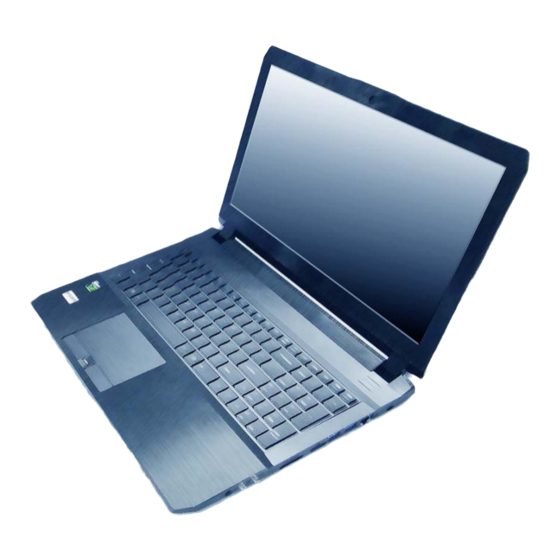
Summary of Contents for Clevo N170RF
- Page 1 N170RF / N171RF...
- Page 2 Preface Notice The company reserves the right to revise this publication or to change its contents without notice. Information contained herein is for reference only and does not constitute a commitment on the part of the manufacturer or any subsequent ven- dor.
- Page 3 This manual is intended for service personnel who have completed sufficient training to undertake the maintenance and inspection of personal computers. It is organized to allow you to look up basic information for servicing and/or upgrading components of the N170RF / N171RF series notebook PC.
-
Page 4: Important Safety Instructions
Preface IMPORTANT SAFETY INSTRUCTIONS Follow basic safety precautions, including those listed below, to reduce the risk of fire, electric shock and injury to per- sons when using any electrical equipment: 1. Do not use this product near water, for example near a bath tub, wash bowl, kitchen sink or laundry tub, in a wet basement or near a swimming pool. -
Page 5: Instructions For Care And Operation
Preface Instructions for Care and Operation The notebook computer is quite rugged, but it can be damaged. To prevent this, follow these suggestions: Don’t drop it, or expose it to shock. If the computer falls, the case and the components could be damaged. Do not expose the computer Do not place it on an unstable Do not place anything heavy... -
Page 6: Power Safety
Preface Avoid interference. Keep the computer away from high capacity transformers, electric motors, and other strong mag- netic fields. These can hinder proper performance and damage your data. Take care when using peripheral devices. Use only approved brands of Unplug the power cord before peripherals. - Page 7 Preface Battery Precautions • Only use batteries designed for this computer. The wrong battery type may explode, leak or damage the computer. • Do not continue to use a battery that has been dropped, or that appears damaged (e.g. bent or twisted) in any way. Even if the computer continues to work with a damaged battery in place, it may cause circuit damage, which may possibly result in fire.
-
Page 8: Related Documents
Preface Related Documents You may also need to consult the following manual for additional information: User’s Manual on CD/DVD This describes the notebook PC’s features and the procedures for operating the computer and its ROM-based setup pro- gram. It also describes the installation and operation of the utility programs provided with the notebook PC. System Startup 1. -
Page 9: Specifications
Introduction Specifications Processor Options Video Adapter Intel® Core™ i7 Processor Intel® Integrated GPU and NVIDIA® Discrete GPU i7-6700HQ (2.60GHz) Supports Microsoft Hybrid Graphics 8MB Smart Cache, 14nm, DDR3L-1600MHz, TDP 45W Intel Integrated GPU Intel® Core™ i5 Processor Latest Specification Information i5-6300HQ (2.30GHz) Dynamic Frequency The specifications listed here are correct at the... - Page 10 Introduction Pointing Device Communication Built-in Touchpad Built-In Gigabit Ethernet LAN 2.0M FHD PC Camera Module Interface WLAN/ Bluetooth M.2 Modules: Four USB 3.0 Ports (Factory Option) Intel® Wireless-AC 8260 Wireless LAN One Mini DisplayPort 1.2 (802.11ac) + Bluetooth 4.1 One HDMI-Out Port (Factory Option) Intel®...
-
Page 11: External Locator - Top View With Lcd Panel Open
Introduction External Locator - Top View with LCD Panel Open Figure 1 Top View 1. PC Camera 2. *PC Camera LED *When the PC camera is in use, the LED will be illuminated. 3. Built-In Array Microphone 4. LCD 5. Speakers 6. -
Page 12: External Locator - Front & Right Side Views
Introduction External Locator - Front & Right Side Views Figure 2 Front View 1. LED Indicator FRONT VIEW Figure 3 Right Side View 1. Multi-in-1 Card RIGHT SIDE VIEW Reader 2. USB 3.0 Port 3. External Monitor Port 4. RJ-45 LAN Jack External Locator - Front &... -
Page 13: External Locator - Left Side & Rear View
Introduction External Locator - Left Side & Rear View Figure 4 Left Side View 1. Security Lock Slot 2. USB 3.0 Ports 3. S/PDIF-Out Jack LEFT SIDE VIEW 4. Microphone-In Jack 5. Headphone-Out Jack 6. Optical Device Drive Bay 7. Emergency Eject Hole Figure 5 REAR VIEW... -
Page 14: External Locator - Bottom View
Introduction External Locator - Bottom View Figure 6 Bottom View 1. Vent 2. Battery 3. HDD Bay Overheating To prevent your com- puter from overhea- ting, make sure no- thing blocks any vent while the computer is in use. External Locator - Bottom View 1 - 7... -
Page 15: Maintenance Tools
Disassembly NOTE: All disassembly procedures assume that the system is turned OFF, and disconnected from any power supply (the battery is removed too). Maintenance Tools The following tools are recommended when working on the notebook PC: • M3 Philips-head screwdriver •... -
Page 16: Maintenance Precautions
Disassembly Maintenance Precautions The following precautions are a reminder. To avoid personal injury or damage to the computer while performing a re- moval and/or replacement job, take the following precautions: Power Safety Warning 1. Don't drop it. Perform your repairs and/or upgrades on a stable surface. If the computer falls, the case and other Before you undertake components could be damaged. -
Page 17: Disassembly Steps
Disassembly Disassembly Steps The following table lists the disassembly steps, and on which page to find the related information. PLEASE PERFORM THE DISASSEMBLY STEPS IN THE ORDER INDICATED. To remove the Battery: To remove the M.2 SSD: 1. Remove the battery page 2 - 5 1. -
Page 18: Removing The Battery
Disassembly Removing the Battery Figure 1 Battery Removal 1. Turn the computer off, and turn it over. 2. Locate the battery and remove screws (Figure 1a). a. Remove the screws. 3. Carefully lift the battery up in the direction of the arrow (Figure 1b b. -
Page 19: Removing The Keyboard
Disassembly Removing the Keyboard Figure 2 Keyboard Removal 1. Turn off the computer, turn it over to remove the battery (page 2 - 2. Remove screws (screw size = M2.5x5L) and the component bay cover (Figure 3a). a. Remove the screws and 3. - Page 20 Disassembly 6. Carefully lift the keyboard off the computer (Figure 3e). Figure 3 Keyboard Removal e. Remove the keyboard. Re-inserting the Key- board When re-inserting the keyboard firstly, align the keyboard tabs at the bot- tom of the keyboard with the slots in the case.
-
Page 21: Removing The Hard Disk Drive
Disassembly Removing the Hard Disk Drive Figure 4 The hard disk drive can be taken out to accommodate other 2.5" serial (SATA) hard disk drives with a height of 9.5mm HDD Assembly or 7mm (h). Follow your operating system’s installation instructions, and install all necessary drivers and utilities (as Removal outlined in Chapter 4 of the User’s Manual) when setting up a new hard disk. - Page 22 Disassembly 4. Lift the hard disk assembly out of the bay (Figure 5c Figure 5 5. Remove screws and separate the hard disk from the bracket and mylar cover (Figure 5d HDD Assembly 6. Reverse the process to install a new hard disk (do not forget to insert the mylar cover between the bracket and Removal (cont’d.) hard disk as shown before replacing the screws).
- Page 23 Disassembly Hard Disk Size Note (Foam Rubber Insert) Note that the hard disks pictured on the following pages are all 9.5mm(H) hard disk drives. In some cases 7mm(H) hard disk drives will be installed. Also pay attention on the alignment of the hard disk and bracket when tightening the screws. For more information contact your distributor/supplier, and bear in mind your warranty terms.
-
Page 24: Removing The 2Nd Hard Disk From Caddy Bay
Disassembly Removing the 2nd Hard Disk from Caddy Bay Figure 7 2nd HDD Removal 1. Turn off the computer, remove the battery (page 2 - 5), and bottom case (page 2 - 2. Carefully push out the caddy bay out in the direction of the arrow (Figure 7a a. -
Page 25: Removing The Optical (Cd/Dvd) Device
Disassembly Removing the Optical (CD/DVD) Device Figure 8 Optical Device 1. Turn off the computer, remove the battery (page 2 - 5), and bottom case (page 2 - Removal 2. Remove screw and carefully push the optical device out of the bay at point (Figure 8a 3. -
Page 26: Removing The System Memory (Ram)
Disassembly Removing the System Memory (RAM) Figure 9 RAM Module The computer has two memory sockets for 204 pin Small Outline Dual In-line Memory Modules (SO-DIMM) supporting Removal DDR3L up to 1600 MHz. The main memory can be expanded up to 16GB. The total memory size is automatically de- tected by the POST routine once you turn on your computer. -
Page 27: Removing The M.2 Ssd Module
Disassembly Removing the M.2 SSD Module Figure 10 M.2 SSD Module 1. Turn off the computer, remove the battery (page 2 - 5), keyboard (page 2 - 6) and bottom case (page 2 - Removal 2. The M.2 SSD module will be visible at point on the mainboard (Figure 10a). -
Page 28: Removing The Wireless Lan Module
Disassembly Removing the Wireless LAN Module Figure 11 Wireless LAN 1. Turn off the computer, remove the battery (page 2 - 5), keyboard (page 2 - 6) and bottom case (page 2 - Module Removal 2. The Wireless LAN module will be visible at point on the mainboard (Figure 11a). -
Page 29: Wireless Lan, & Combo Module Cables
Disassembly Wireless LAN, & Combo Module Cables Note that the cables for connecting to the antennae on WLAN, WLAN & Bluetooth Combo, 3G and LTE modules are not labelled. The cables/covers (each cable will have either a black or transparent cable cover) are color coded for iden- tification as outlined in the table below.
Need help?
Do you have a question about the N170RF and is the answer not in the manual?
Questions and answers