Table of Contents

Related Manuals for Zte ZXDU58 B900


Summary of Contents for Zte ZXDU58 B900
- Page 1 ZXDU58 B900 DC Power System Product Description Version: V4.5R01M01 ZTE CORPORATION NO. 55, Hi-tech Road South, ShenZhen, P.R.China Postcode: 518057 Tel: +86-755-26771900 Fax: +86-755-26770801 URL: http://ensupport.zte.com.cn E-mail: support@zte.com.cn...
- Page 2 ZTE CORPORATION is prohibited. Additionally, the contents of this document are protected by contractual confidentiality obligations. All company, brand and product names are trade or service marks, or registered trade or service marks, of ZTE CORPORATION or of their respective owners.
-
Page 3: Table Of Contents
4.1 Technical Specifications..................4-1 4.2 Internal Protection Functions................4-2 4.3 Output Power Control ..................4-5 Chapter 5 Configuration List ..............5-1 Chapter 6 Alarm List .................. 6-1 Appendix A Electrical Connection Diagram ........... A-1 Glossary ......................I SJ-20121116145308-001|2012-12-05 (R1.0) ZTE Proprietary and Confidential... - Page 4 SJ-20121116145308-001|2012-12-05 (R1.0) ZTE Proprietary and Confidential...
-
Page 5: About This Manual
Purpose This manual applies to the ZXDU58 B900 (V4.5R01M01) DC Power System (the ZXDU58 B900 system for short). The ZXDU58 B900 system provides power for -48 V communications equipment. This manual describes the structure, characteristics, and specifications of the ZXDU58 B900 system. - Page 6 Variables in commands. It may also refer to other related manuals and documents. Bold Menus, menu options, function names, input fields, option button names, check boxes, drop-down lists, dialog box names, window names, parameters, and commands. Note: provides additional information about a certain topic. SJ-20121116145308-001|2012-12-05 (R1.0) ZTE Proprietary and Confidential...
-
Page 7: System Introduction
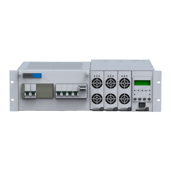
System Introduction....................1-1 System Features ......................1-1 1.1 System Introduction The ZXDU58 B900 system is designed to be installed in a cabinet. It is 19 inches in width and 3U in height. The system can provide power for -48 V communications equipment. - Page 8 ZXDU58 B900 Product Description Compact structure design. The ZXDU58 B900 chassis is 3U in height and 19 inches in width. It is designed to be installed into a cabinet. SJ-20121116145308-001|2012-12-05 (R1.0) ZTE Proprietary and Confidential...
-
Page 9: Chapter 2 System Structure And Components
System Structure......................2-1 ZXD030 S480 Rectifier....................2-3 Centralized Supervision Unit ..................2-5 Signal Interfaces on the SIB ..................2-6 2.1 System Structure For the structure of the ZXDU58 B900 system, see Figure 2-1. For a description of the system components, refer to Table 2-1. - Page 10 To turn on/off AC input live wires. When the AC input breaker is turned on, the rectifiers automatically turn on. AC output circuit breaker To turn on/off AC output of ZXDU58 B900. AC SPD Provides AC input surge protection. DC output circuit breakers To turn on/off DC output with overload protection.
-
Page 11: Zxd030 S480 Rectifier
This setion is applicable to ZXD030 S480 (V1.0) rectifier. The ZXD030 S480 rectifiers convert AC to DC, power DC loads and charge the batteries. Appearance For the appearance of the ZXD030 S480 rectifier, see Figure 2-4. SJ-20121116145308-001|2012-12-05 (R1.0) ZTE Proprietary and Confidential... - Page 12 ZXDU58 B900 Product Description Figure 2-4 ZXD030 S480 (V1.0) Rectifier Indicators The indicators display the operational status of the rectifier. For the indicators of the rectifier, see Figure 2-5. For a description of the working status of the indicators, refer Table 2-4.
-
Page 13: Centralized Supervision Unit
Other fault 2.3 Centralized Supervision Unit The Centralized Supervision Unit (B900-CSU) manages the power distribution unit, rectifiers and batteries of the ZXDU58 B900 system. Functions Gives an audible and visual alarm and provides the protection function when the system is faulty. -
Page 14: Signal Interfaces On The Sib
Buttons and LCD The buttons and the LCD of the CSU enable the users to query operational data of the ZXDU58 B900 system, set parameters, and control the operation of the ZXDU58 B900 system. The button names are as follows: ▲/▼: up/down... - Page 15 Ambient temperature Connects to environment temperature sensor. Door status alarm Connects to door entrance detect sensor. Flood alarm Connects to flood detect sensor. Smoke alarm Connects to smoke detect sensor. Input and output relay interfaces SJ-20121116145308-001|2012-12-05 (R1.0) ZTE Proprietary and Confidential...
- Page 16 ZXDU58 B900 Product Description Interface Description Input relay 1 and 2 The four input relays can be customized by the user for alarm input. Input relay 3 and 4 The default alarm status of the input relays in the CSU are “close”.
-
Page 17: Chapter 3 System Specifications
System Specifications Table of Contents Environment Specifications ..................3-1 Technical Specifications .....................3-1 Compliance Standards ....................3-3 3.1 Environment Specifications For the description of environment specifications of the ZXDU58 B900 system, refer to Table 3-1. Table 3-1 Environment Specifications Item Specification Operational temperature -5 ℃... - Page 18 ZXDU58 B900 Product Description Table 3-2 System Specifications Item Specification Rated output current 90 A (when fully configured) System efficiency ≥ 93% Noise ≤ 55 dB(A) Monitoring networking mode RS232/RS485 serial port, and transparent transmission with the communication equipment Mean Time Between ≥...
-
Page 19: Compliance Standards
This device complies with Part 15 of the FCC Rules and is subject to the following two conditions: (1) this device may not cause harmful interference, and (2) this device must accept any interference received, including interference that may cause undesired operations. SJ-20121116145308-001|2012-12-05 (R1.0) ZTE Proprietary and Confidential... - Page 20 ZXDU58 B900 Product Description This page intentionally left blank. SJ-20121116145308-001|2012-12-05 (R1.0) ZTE Proprietary and Confidential...
-
Page 21: Chapter 4 Zxd030 S480 Rectifier Specifications
Rated output voltage: 48 V DC Output voltage range: 42 V to 58 V (adjusted through the monitoring unit of the power system) Output current limit 3 A to 35 A, can be set through the monitoring unit. SJ-20121116145308-001|2012-12-05 (R1.0) ZTE Proprietary and Confidential... -
Page 22: Internal Protection Functions
ZXDU58 B900 Product Description Item Description In case of current limit, flyback occurs when the output voltage falls below 40 V. Voltage stabilizing accuracy ≤ ±0.6% Output weighted noise ≤ 2 mV Broad frequency noise ≤ 30 mV (3.4 kHz~150 kHz) voltage ≤... - Page 23 AC input voltage recovers. The different operational status are implemented by internal monitoring components (the voltage precision is ±5 V AC), see Figure 4-1. Figure 4-1 AC Input Over/Under-Voltage Protection SJ-20121116145308-001|2012-12-05 (R1.0) ZTE Proprietary and Confidential...
- Page 24 ZXDU58 B900 Product Description PFC Output Over/Under-Voltage Protection output over/under-voltage protection is described as follows, these protection functions are implemented through hardware. The voltage precision is ±10 V DC and the flyback width is (15±10) V DC. When the PFC output voltage > 440 V DC, the back DC-DC conversion circuit and the front PFC circuit stop working, and the Power indicator turns off while the Alarm indicator turns on.
-
Page 25: Output Power Control
In the case of the AC input voltage falls in the range 165 V ~ 295 V with the maximum output power 1740 W provided, if the load keeps increasing, the output voltage will decrease. And the maximum output power decreases consequently. For a detailed curve, see Figure 4-3. SJ-20121116145308-001|2012-12-05 (R1.0) ZTE Proprietary and Confidential... - Page 26 ZXDU58 B900 Product Description When the DC output voltage falls in the range of 50 V ~ 58 V, the output power is 1740 W. For example, when the DC output voltage is 58 V, the output current is 30 A; when the DC output voltage is 58 V, the output current is 34.8 A.
- Page 27 66.67% when the temperature is 70 ℃. > 70 ℃ 0 (the rectifier shuts down for protection against over-temperature) • The maximum output power of the rectifier is 1740 W. SJ-20121116145308-001|2012-12-05 (R1.0) ZTE Proprietary and Confidential...
- Page 28 ZXDU58 B900 Product Description This page intentionally left blank. SJ-20121116145308-001|2012-12-05 (R1.0) ZTE Proprietary and Confidential...
-
Page 29: Chapter 5 Configuration List
Chapter 5 Configuration List Table 5-1 describes the ZXDU58 B900 system configuration. Table 5-1 Configuration List Item Configuration Chassis One embedded chassis Rectifier ZXD030 S480 (V1.0) rectifiers; three sets (maximum) Centralized Supervision Unit B900-CSU (software version: V1.20) AC Power AC input... - Page 30 ZXDU58 B900 Product Description This page intentionally left blank. SJ-20121116145308-001|2012-12-05 (R1.0) ZTE Proprietary and Confidential...
-
Page 31: Chapter 6 Alarm List
The AC input current is higher than Default relay: 0 AC.OverCurr. SMR Over-Vout Default level: Major The output voltage of the rectifier is higher Default relay: A2 than the threshold, and the rectifier stops output. SJ-20121116145308-001|2012-12-05 (R1.0) ZTE Proprietary and Confidential... - Page 32 ZXDU58 B900 Product Description S.N. Alarm Name Alarm Level and Output Relay Alarm Description SMR Over-Iout Default level: Major The output current of the rectifier is higher Default relay: A2 than the threshold, and the rectifier stops output. SMR Fan Fault Default level: Major The fan of the rectifier is faulty.
- Page 33 The door with the door magnet switch is Default relay: 0 opened. Some object intrudes. E.T.Invalid Default level: Mask The environment temperature detection is Default relay: 0 invalid. E.H.Invalid Default level: Mask The environment humidity detection is invalid. Default relay: 0 SJ-20121116145308-001|2012-12-05 (R1.0) ZTE Proprietary and Confidential...
- Page 34 ZXDU58 B900 Product Description This page intentionally left blank. SJ-20121116145308-001|2012-12-05 (R1.0) ZTE Proprietary and Confidential...
-
Page 35: Appendix A Electrical Connection Diagram
Appendix A Electrical Connection Diagram For the simplified block diagram of the ZXDU58 B900 system operating principles, see Figure A-1. Figure A-1 Operating Principles of the System The system components are described as follows. AC distribution unit: The AC distribution unit connects AC input to the system and distributes AC power. - Page 36 Figure A-2 Electrical Connection Diagram of the ZXDU58 B900 (V4.5R01M01) System...
-
Page 37: Glossary
- Load Low Voltage Disconnect - Miniature Circuit Breaker MTBF - Mean Time Between Failures - Power Factor Correction RoHS - Restriction of Hazardous Substances - Supervision Center - Signal Interface Board - Surge Protection Device SJ-20121116145308-001|2012-12-05 (R1.0) ZTE Proprietary and Confidential...
Need help?
Do you have a question about the ZXDU58 B900 and is the answer not in the manual?
Questions and answers