Advertisement
Advertisement
Table of Contents

Subscribe to Our Youtube Channel
Related Manuals for Zte ZXDU68 B201


Summary of Contents for Zte ZXDU68 B201
- Page 1 ZXDU68 B201 DC Power System Product Description Version: V5.0R06M09 ZTE CORPORATION NO. 55, Hi-tech Road South, ShenZhen, P.R.China Postcode: 518057 Tel: +86-755-26771900 Fax: +86-755-26770801 URL: http://ensupport.zte.com.cn E-mail: support@zte.com.cn...
- Page 2 ZTE CORPORATION is prohibited. Additionally, the contents of this document are protected by contractual confidentiality obligations. All company, brand and product names are trade or service marks, or registered trade or service marks, of ZTE CORPORATION or of their respective owners.
-
Page 3: Table Of Contents
4.1 Technical Specifications..................4-1 4.2 Input Features....................4-3 4.3 Output Features ....................4-4 4.4 Power Decrease With High Temperature ............. 4-5 Chapter 5 Alarm List .................. 5-1 Appendix A Electrical Connection Diagram ........... A-1 Glossary ......................I SJ-20120703093141-002|2013-01-08 (R1.2) ZTE Proprietary and Confidential... - Page 4 SJ-20120703093141-002|2013-01-08 (R1.2) ZTE Proprietary and Confidential...
-
Page 5: About This Manual
About This Manual Purpose This manual applies to the ZXDU68 B201 (V5.0R06M09) DC Power System. The ZXDU68 B201 system is designed to be installed in a cabinet/rack and provides power for -48 V communications equipment. This manual describes the system structure, characteristics, and configuration. - Page 6 SJ-20120703093141-002|2013-01-08 (R1.2) ZTE Proprietary and Confidential...
-
Page 7: Chapter 1 System Overview
System Introduction....................1-1 System Features ......................1-1 1.1 System Introduction The ZXDU68 B201 system is designed to be installed in a cabinet/rack. ZXDU68 B201 is 19 inches in width and 5U in height. The system can provide power for -48 V communications equipment. - Page 8 ZXDU68 B201 Product Description With 50% - 100% output power, the rectifier efficiency is ≥ 96%. Automatically Switching the Rectifiers to the Sleep Mode The system switches one or more rectifiers to the sleep mode according to the load power.
-
Page 9: Chapter 2 System Structure And Components
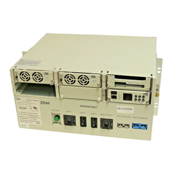
Table of Contents System Structure......................2-1 ZXD3000 Rectifier ......................2-4 Centralized Supervision Unit ..................2-6 Signal Interface Unit ....................2-7 2.1 System Structure For the structure of the ZXDU68 B201 chassis, see Figure 2-1 Figure 2-2. Front View Figure 2-1 Chassis Structure (Front View) 1. - Page 10 ZXDU68 B201 Product Description Table 2-1 Chassis Components (Front View) S.N. Component Description ZXD3000 (V5.0) rectifiers Convert AC power to DC power. For further details, refer to 2.2 ZXD3000 Rectifier. Signal Interface Unit (SIU) Provides signal interfaces for supervision. For further details, refer to 2.4 Signal Interface...
- Page 11 Cabling hole for the AC input cables (L, N, L, N, PE) Battery input connection Connect battery packs to the system. terminals (BATT1, BATT2, BATT3) (-48V) Main DC output connection Connect -48 V terminals of the main DC load. terminals (MAIN OUTPUT) (-48V) SJ-20120703093141-002|2013-01-08 (R1.2) ZTE Proprietary and Confidential...
-
Page 12: Zxd3000 Rectifier
ZXDU68 B201 Product Description S.N. Component Description -48V busbar (-48V) Working ground busbar Connects +/RTN cables of battery packs and DC loads. (+/RTN) AC input connection Connect AC input cables (L, N, L, N, PE). terminals (L, N, L, N,... - Page 13 2-4. For a description of the pin definitions, refer to Table 2-4. The interfaces complete the electrical and signal connections between the rectifier and the ZXDU68 B201 power system. Figure 2-4 Rectifier Interfaces Table 2-4 Pin Definitions of Rectifier Interfaces Interface Name Pin No.
-
Page 14: Centralized Supervision Unit
Transmits data to the background Supervision Center (SC) and receives commands from the SC. In this way, the ZXDU68 B201 system can be monitored remotely. The CSU can be remotely managed through a computer installed with web browser anywhere if Ethernet is available. -
Page 15: Signal Interface Unit
The Ethernet interface supports multiple monitoring networking modes through à Telnet, HTTP, and SNMP. Indicators The indicators display the operational status of the CSU and the ZXDU68 B201 system. For a description of indicators, refer to Table 2-5. Table 2-5 CSU Operational Status... - Page 16 ZXDU68 B201 Product Description Figure 2-6 Signal Interface Unit (SIU) 1. SIB 2. Interface designation The SIB provides various supervision interfaces including input and output relay interfaces, background communication interfaces, and environment detection interfaces. For the layout of the interfaces on the SIB, see Figure 2-7.
- Page 17 To connect the temperature sensor for battery pack 2 Battery 3 temperature To connect the temperature sensor for battery pack 3 Battery 4 temperature To connect the temperature sensor for battery pack 4 Environment temperature To connect an ambient temperature sensor SJ-20120703093141-002|2013-01-08 (R1.2) ZTE Proprietary and Confidential...
- Page 18 ZXDU68 B201 Product Description This page intentionally left blank. 2-10 SJ-20120703093141-002|2013-01-08 (R1.2) ZTE Proprietary and Confidential...
- Page 19 System Specifications Table of Contents Configuration List .......................3-1 Environmental Specifications..................3-2 Technical Specifications .....................3-2 Compliance Standards ....................3-5 3.1 Configuration List For the configuration list of the ZXDU68 B201 system , refer to Table 3-1. Table 3-1 Configuration List Component Configuration Chassis Rectifier ZXD3000 (V5.0)
-
Page 20: Technical Specifications
A/2P circuit breaker Auxiliary DC output: One 50 A DC output connector DC SPD None 3.2 Environmental Specifications For a description of the environmental specifications of the ZXDU68 B201 system, refer Table 3-2. Table 3-2 Environmental Specifications Item Specifications Operating temperature -4 °F to +131 °F/-20 °C to +55 °C (+59 °F to +77 °F/+15 °C to...
Need help?
Do you have a question about the ZXDU68 B201 and is the answer not in the manual?
Questions and answers