Advertisement
Quick Links
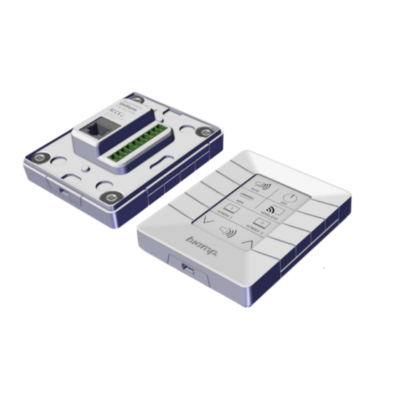
Impera
Installation and Set Up Guide
INSTALLATION
Intended for wall mounting on vertical surfaces. Uses an E-ink display.
•
I/O, RS-232/IR terminal connections, and LAN port are located on the back
•
of the unit.
The controller is PoE powered: Use an IEE802.3-compliant PoE power
•
supply or switch. PoE injector not included.
The E-ink display, button functions, and LED indicators are configured
•
using Biamp Project Designer Software available on Biamp.com
INCLUDED IN THE BOX
support@biamp.com
CONSIDERATIONS
Uniform
AV Control Pad
www.biamp.com
Advertisement

Related Manuals for Biamp Impera Uniform


Summary of Contents for Biamp Impera Uniform
- Page 1 The controller is PoE powered: Use an IEE802.3-compliant PoE power • supply or switch. PoE injector not included. The E-ink display, button functions, and LED indicators are configured • using Biamp Project Designer Software available on Biamp.com INCLUDED IN THE BOX support@biamp.com www.biamp.com...
-
Page 2: Device Layout
I/O 2 I/O 1 1. 2 RS-232 or IR ports, unidirectional Ground 2. 1 RS-232 bidirectional port or IR unidirectional 3. 1 RJ-45 Network (LAN) port with PoE functionality 4. 3 Digital input/output ports Impera Uniform Installation and Set Up Guide... - Page 3 EU 1 – gang Alignment holes – do electrical box not insert screws or EU 1 – gang other fasteners here! electrical box Wall Mount Hole Wall Mount Hole DK 1.5M – gang electrical box Impera Uniform Installation and Set Up Guide...
- Page 4 US 1-Gang Mounting Plate Purchased separately. For fastening to a US-1 compliant gang box. The controller attaches magnetically to this plate. US 1 – gang electrical box US-1 gang electrical box Impera Uniform Installation and Set Up Guide...
-
Page 5: Installation Overview
• To a PoE source using the LAN port • To any terminal connections for the AV system An overview of the Controller connector ports starts on page 15. Attach the controller to the mounting plate, page 12. Impera Uniform Installation and Set Up Guide... - Page 6 The controller is designed to be mounted on a wall in a vertical orientation between 145 and 102 centimeters (65 to 40 inches) above the floor depending on the height of your typical users. Impera Uniform Installation and Set Up Guide...
- Page 7 2. Position the plate on the electrical box. 3. Use two of the included screws to secure the mounting plate to the gang box. 4. Advance to the Connect the Controller procedure on page 11. Impera Uniform Installation and Set Up Guide...
- Page 8 2. Position the plate on the electrical box. 3. Use two of the screws to secure the mounting plate to the gang box. 4. Advance to the Connect the Controller procedure on page 11. Impera Uniform Installation and Set Up Guide...
- Page 9 5. Drill the holes and insert any required wall plugs. 6. Use the 4 included screws or another appropriate fastener type to secure the mounting plate to the wall. 7. Advance to the Connect the Controller procedure on page 11. Impera Uniform Installation and Set Up Guide...
- Page 10 2. Position the plate on the electrical box. 3. Use two of the included screws to secure the mounting plate to the gang box. 4. Advance to the Connect the Controller procedure on page 11. Impera Uniform Installation and Set Up Guide...
- Page 11 • The port’s LED indicator visual outputs are described on page 18. 2. Make any required system terminal connections with the controller. • See the Ports appendix for details on port functionality. Page 15. Impera Uniform Installation and Set Up Guide...
- Page 12 Detaching: To detach the controller, use both hands to grasp the controller on each side. Pull it straight out from the wall, exercising caution to protect the connected LAN ethernet cable and any terminal connections. Impera Uniform Installation and Set Up Guide...
-
Page 13: Controller Setup
Project Designer provides drag-and-drop functionality for configuring the controller’s graphical user interface (GUI) and hardware functions. See the next page for specifics. Project Designer also provides the following: • An extensive driver library for incorporating Biamp and third-party devices in the AV system. • Automated generation of project documentation. -
Page 14: Configure The Controller
Configure the Controller 1. Use the Biamp Project Designer software to create a configuration file for the controller and the AV system it will control. Controller Configuration • Set up the graphical user interface on the controller E-ink display. • Assign functions to the hardware buttons. - Page 15 This port can be connected to devices requiring a reply function such as projectors. Connection Configurations Bidirectional RS232 communications example. Ground to Pin 5 Tx-1 to Pin 3 Rx-1 to Pin 2 Grnd TX-1 RX-1 Impera Uniform Installation and Set Up Guide...
- Page 16 TX-2 Ground to IR Emitter Tx-2 striped wire to IR Emitter Dual IR Port IR 2 Emitter Ground to IR 2 Emitter Grnd Junction Tx-2 to IR 1 Emitter TX-2 IR 1 Emitter Impera Uniform Installation and Set Up Guide...
- Page 17 Inputs: When used as inputs, the applied voltage must be below 1 VDC to be accepted as LOW, and above 4 VDC (but below 24 VDC) to be accepted as HIGH. The inputs are default HIGH and must be connected to a ground to change state. Impera Uniform Installation and Set Up Guide...
-
Page 18: Ethernet Port (Lan)
This port provides power over Ethernet to the controller. Powering the controller requires one of the following • A PoE-enabled switch compliant with an IEE802.3 • A PoE power injector compliant with IEE802.3 Impera Uniform Installation and Set Up Guide... - Page 19 • The controller can be powered using this port while uploading a configuration file. • Uploads can also be safely performed using this port while the controller is connected to a LAN ethernet cable that is supplying power. Impera Uniform Installation and Set Up Guide...
- Page 20 The LEDs embedded in buttons 1 – 4 on the front left side of the controller flash error codes in the event of a system fault or a reset to the factory default settings. LED Indicators Continued on the next page Impera Uniform Installation and Set Up Guide...
- Page 21 • Power cycle: Turn off power to the controller for a minimum of 20 seconds. Then repower the controller. • If the power cycle option fails, you may restore the controller to its factory settings. See the Restoring factory settings indicator description on page 23. Impera Uniform Installation and Set Up Guide...
- Page 22 • Verify that the serial number used in Project Designer matches the Biamp extension unit. • Check the network or RS-232 connection from the Controller to the Biamp extension unit. LED Pattern Error The wrong firmware version is loaded in the Biamp extension unit. Flashing Flashing Flashing Solution •...
- Page 23 LED Pattern Error Serial number error. Flashing Solutions • Return the controller to Biamp or your audio / visual dealer for replacement or repair. LED Pattern Restore Operation Flashing The controller is resetting to the factory settings. Flashing Solution • This should only be done to return functionality to the Controller in the event it locks up and displays the “unexpected error”...
- Page 24 Off button is Flashing 6. flashing 4 times per second. Flashing 7. Flashing 8. Solution • Verify the password is entered correctly in Project Designer for all LAN devices that require a password. Impera Uniform Installation and Set Up Guide...
- Page 25 • Please see the label on the back of the device for the other logos and legends. • Biamp’s universal safety and compliance statements and marks are available in the Safety, Compliance, and Warranty Guide included with this device.
- Page 26 Support@biamp.com 9300 SW Gemini Drive Beaverton, OR 978008 USA Warranty: biamp.com/legal/warranty-information Safety & Compliance: biamp.com/compliance January 5, 2022...
Need help?
Do you have a question about the Impera Uniform and is the answer not in the manual?
Questions and answers