Siemens SITRANS AS100 Operating Instructions Manual
Acoustic sensors
Hide thumbs
Also See for SITRANS AS100:
- Instruction manual (20 pages) ,
- Operating instructions manual (34 pages)
Table of Contents

Related Manuals for Siemens SITRANS AS100


Summary of Contents for Siemens SITRANS AS100
- Page 1 Introduction Installation SITRANS Mounting Connecting Acoustic Sensors SITRANS AS100 Applications Specifications Operating Instructions Technical data and dimensions Product documentation and support 04/2021 A5E31952194-AC...
- Page 2 Note the following: WARNING Siemens products may only be used for the applications described in the catalog and in the relevant technical documentation. If products and components from other manufacturers are used, these must be recommended or approved by Siemens. Proper transport, storage, installation, assembly, commissioning, operation and maintenance are required to ensure that the products operate safely and without any problems.
-
Page 3: Table Of Contents
Mounting ............................... 7 Connecting ............................11 Applications ............................14 Specifications ............................18 Technical data and dimensions ......................20 Product documentation and support ....................25 Product documentation ..................... 25 Technical support ......................26 Index ..............................27 SITRANS AS100 Operating Instructions, 04/2021, A5E31952194-AC... -
Page 4: Introduction
Note • The SITRANS AS100 is to be used only in the manner outlined in this manual • This product is intended for use in industrial areas. Operation of this equipment in a residential area may cause interference to several frequency based communications Features •... -
Page 5: Installation
• joints and interfaces attenuate the acoustic emission levels. • minimal temperature variation where acoustic emission levels are weak. • location should provide sufficient response time in alarm or control circuit. e.g. loss of bearing lubrication, plug chute detection. SITRANS AS100 Operating Instructions, 04/2021, A5E31952194-AC... - Page 6 Good friction between product and pip- Minimal amount of acoustic emission ing. Mount Sensor on the upstream side activity due to limited friction between of gasket for highest level of acoustic product and piping. emission activity. SITRANS AS100 Operating Instructions, 04/2021, A5E31952194-AC...
-
Page 7: Mounting
Mounting Note • To ensure the most ideal location, test the SITRANS AS100 by clamping the Sensor to the application, and running a trial period to determine the system's performance. The acoustic emission level can be monitored by a voltmeter across the analog output. Refer to Interconnection (Page 11). - Page 8 • If welding, weld must be a continuous bead. Tacking does not provide sufficient acoustical coupling. • Do not arc weld on equipment connected to a SITRANS AS100. Remove the SITRANS AS100 or disconnect electrically to avoid current flowing through the sensor.
- Page 9 7. Install the sleeve over the tapered steel part, and thread the remaining two parts of the gland onto the cable. 8. Tighten the assembly to ensure a seal of the gland over the cable with outer jacket. SITRANS AS100 Operating Instructions, 04/2021, A5E31952194-AC...
- Page 10 For standard Temperature range model, If the flange temperature is 100°C and the maximum temperature is 80°C. ambient temperature is 20°C, the Sensor temperature at the electronics is below the maximum rating. *maximum range dependent on model. SITRANS AS100 Operating Instructions, 04/2021, A5E31952194-AC...
-
Page 11: Connecting
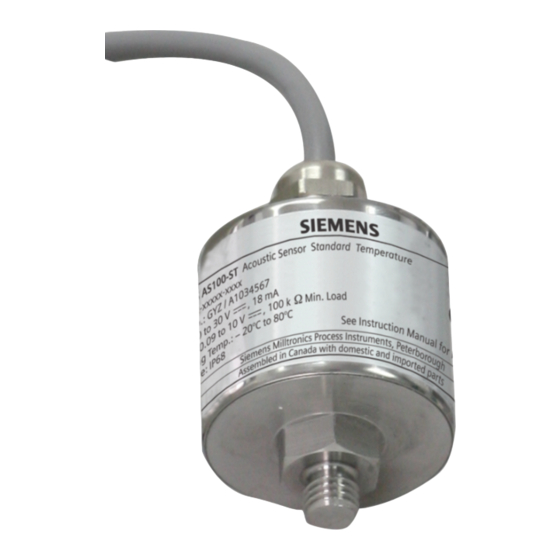
Connecting SITRANS AS100 Standard Temperature Version (ST) ① Vsup: 20 to 30 V DC supply input ② Vsens: analog output 0.08 to 10 V DC nominal ③ shield--tied to Sensor casing *Sensor range selection high sensitivity range = red and green to Vsup +... - Page 12 This table provides a guideline for suitable wire gauges where distances are considerable. Maximum distance between Sensor and supply (24V or Control Unit) wire size distance meters feet 7 x 0.20 0.22 1600 7 x 0.25 0.35 2600 10 x 0.25 1200 3900 SITRANS AS100 Operating Instructions, 04/2021, A5E31952194-AC...
- Page 13 However, it is important to be aware of the effect. The sensitivity of the SITRANS AS100 Sensor decreases with increasing temperatures at a rate of approximately 0.5% per degree Celsius.
-
Page 14: Applications
Sensor, an alarm in the control room informs the operator of a possible blockage. Recommended location is any point along the under side of chute, where there is friction due to the flow of material. SITRANS AS100 Operating Instructions, 04/2021, A5E31952194-AC... - Page 15 Sensor mounted to each leg of the diverter indicates the presence or absence of flow in the open leg. Low alarm gives early indication of problems in the diverter gate or slide gate, or of blockage or material shortage in the hopper. Leak detection SITRANS AS100 Operating Instructions, 04/2021, A5E31952194-AC...
- Page 16 Applications Cavitation Monitoring Install the SITRANS AS100 Sensor in B either A or B locations. Machine Condition Monitoring Install the SITRANS AS100 Sensor in either A or B locations. Manufactured Date To identify when the product was built use the tables below based on the serial number on the product.
- Page 17 2015 2016 2017 2018 2019 ALPHA CODE Month of Manufacture (one character alpha or numeric entry) Jan. Feb. Mar. Apr. Jun. Jul. Aug. Sept. Oct. Nov. Dec. Day of Manufacture (two character numerical entry) SITRANS AS100 Operating Instructions, 04/2021, A5E31952194-AC...
-
Page 18: Specifications
Available only for CSA Class II version Not available for hazardous rated versions Relative Sensitivity • 0.5% / °C of reading, average over the operating range Output • analog, 0.08 to 10 V DC nominal, 100 KΩ minimum load impedance SITRANS AS100 Operating Instructions, 04/2021, A5E31952194-AC... - Page 19 FM Class II, Div. 1, Groups E, F, G Canada: CSA Class II, Div. 1, Groups E, F, G Russia 1Ex db IIC T4 Gb Ex tb IIIC T100°C Db Ex tc IIIC T100°C Dc SITRANS AS100 Operating Instructions, 04/2021, A5E31952194-AC...
-
Page 20: Technical Data And Dimensions
Technical data and dimensions SITRANS AS100 (ST and ET versions) ① 6 x 24 AWG cable ② Mounting post, 17A/F nut and M10 thread SITRANS AS100 Operating Instructions, 04/2021, A5E31952194-AC... - Page 21 Technical data and dimensions SITRANS AS100 (CSA/FM Class II Rated ST and ET versions) ① 6 x 24 AWG cable ② ½" NPT (CSA and FM approvals) or M20 (ATEX approval) female conduit fitting ③ Mounting post, 17A/F nut and M10 thread...
- Page 22 Technical data and dimensions SITRANS AS100 (ATEX II 2GD version) WARNING Do not open when an explosive atmosphere is present. Possible static hazard. Do not rub or clean the product on site. ① Cable entry (2) M20 x 1.5 ② Enclosure...
- Page 23 Technical data and dimensions Accessories Extension Tab (optional, not available for ATEX II 2GD version) ① SITRANS AS100 mounting hole M10 thread ② Bolt hole, 14mm (0.55")Ø SITRANS AS100 Operating Instructions, 04/2021, A5E31952194-AC...
- Page 24 Technical data and dimensions Mounting Disc (optional, not available for ATEX II 2GD version) ① SITRANS AS100 mounting hole M10 thread Note Both Tab and Disc are 304SS. SITRANS AS100 Operating Instructions, 04/2021, A5E31952194-AC...
-
Page 25: Product Documentation And Support
Entering a serial number 1. Open the PIA Life Cycle Portal (https://www.pia-portal.automation.siemens.com). 2. Select the desired language. 3. Enter the serial number of your device. The product documentation relevant for your device is displayed and can be downloaded. -
Page 26: Technical Support
In addition to our technical support, Siemens offers comprehensive online services at Service & Support (http://www.siemens.com/automation/service&support). Contact If you have further questions about the device, contact your local Siemens representative at Personal Contact (http://www.automation.siemens.com/partner). To find the contact for your product, go to "all products and branches" and select "Products &... -
Page 27: Index
Customer Support, (Refer to Technical support) Service and support Internet, 26 SITRANS AS100 (ATEX II 2GD version), 22 SITRANS AS100 (CSA/FM Class II Rated ST and ET Direct Mounting, 7 versions), 21 Diverter Gate, 15 SITRANS AS100 (ST and ET versions), 20...
Need help?
Do you have a question about the SITRANS AS100 and is the answer not in the manual?
Questions and answers