Advertisement
INSTALLATION OVERVIEW
The installation instructions contained in this document are provided as a guide for proper and reliable installation. The
mounting location should be selected and prepared based on the application. All electrical wiring and mounting hardware
(i.e. electrical mounting box, conduit, etc.) should be prepared with consideration of the requirements outlined in the wiring
and mounting diagrams below.
These instructions include information as follows:
Description
Product Configurations
Enclosure Mounting
Installing Individual Relay Cards
Connecting Panel Power
Connecting Lighting Loads
Connecting Low Voltage Inputs
Operating the Panel
Troubleshooting
Panel Specifications
Panel Load Schedule Form
PRECAUTIONS
•
READ AND FOLLOW ALL SAFETY INSTRUCTIONS.
•
CAUTION - RISK OF ELECTRICAL SHOCK. To prevent electrical shock, turn off power at the circuit breaker before
installing or servicing unit. Never wire energized electrical components.
•
NOTICE: For installation by a licensed electrician in accordance with National and/or local Electrical Codes and the
following instructions.
•
CAUTION: USE COPPER CONDUCTOR ONLY.
•
Be sure to read and understand all instructions before installing or servicing unit
•
For Indoor use only. Do not use outdoors.
•
Do not mount near gas or electric heaters.
•
Disconnect switch or a circuit breaker must be provided and marked as the disconnecting device.
•
The use of accessory equipment not recommended by the manufacturer may cause an unsafe condition.
•
Confirm that device ratings are suitable for application prior to installation.
•
No user serviceable parts contained inside unit. Refer all service related questions to the factory.
•
All servicing shall be performed by qualified service personnel.
•
Equipment should be mounted in locations and at heights where it will not readily be subjected to tampering by
unauthorized personnel.
•
Use only approved materials and components (i.e. twist on connectors, electrical box, etc.) as appropriate for
installation.
•
NOTICE: Do not install if product appears to be damaged.
•
If the equipment is used in a manner not specified by the manufacturer, the protection provided by the equipment may
be impaired.
•
Do not use this equipment for other than intended use.
SAVE THESE INSTRUCTIONS!
9601 Dessau Road, Building One | Austin, TX 78754 Toll Free: 888-698-3242 | Fax: 512-450-1215 | www.hubbell-automation.com
™
INSTALLATION INSTRUCTIONS
LIGHTING CONTROL PANELS
3452B 3.17.2016
Advertisement
Table of Contents

Related Manuals for HUBBELL LIGHTING NX HCSPKEY1


Summary of Contents for HUBBELL LIGHTING NX HCSPKEY1
- Page 1 ™ LIGHTING CONTROL PANELS INSTALLATION INSTRUCTIONS INSTALLATION OVERVIEW The installation instructions contained in this document are provided as a guide for proper and reliable installation. The mounting location should be selected and prepared based on the application. All electrical wiring and mounting hardware (i.e.
-
Page 2: Enclosure Mounting
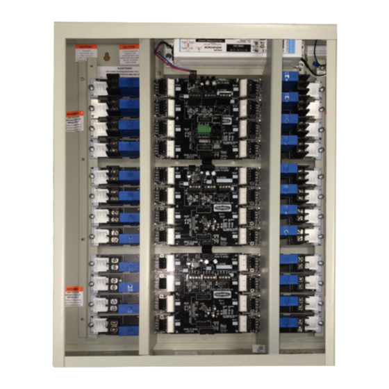
DESCRIPTION The NX Panel is shipped in one package. Panels are configured with all relays of the same type installed or with space only for relays to be installed in the field. The relays are mounted with lighting circuit terminals in the high voltage area. The low voltage control inputs are located in the low voltage area of the panel. -
Page 3: Installing Individual Relay Cards
Locate the enclosure on the mounting surface and use a level to ensure that it is properly oriented and aligned. Secure the enclosure to the mounting surface with hardware as appropriate for the application using the keyed mounting holes as shown below in Figure 2. -
Page 4: Connecting Lighting Loads
CONNECTING LIGHTING LOADS With the power turned off, route the lighting system line and load leads through the high voltage area of the panel shown in Figure 1 on page 2. Connect line and load leads for each lighting load to the output terminals of the appropriate relay as delineated in the project plans and/or Panel Load Schedule. - Page 5 CONNECTING THE HUBBNET™ NETWORK The NX™ Lighting Control Panel is designed to operate as part of a NX Networked Lighting Control system. Once programmed, the panel will operate independently from a network connection. No software installation is required. However, a network connection to the Area Controller is required for programming the panel.
-
Page 6: Troubleshooting
TROUBLESHOOTING A blinking “green” Relay board status LED indicates that communication has not been properly established for this card. Contact Hubbell Control Solutions Technical Service at (800) 888-8006 for assistance and replacement as required. NX™ PANEL SPECIFICATIONS Panel Input Power Requirements: •...
Need help?
Do you have a question about the NX HCSPKEY1 and is the answer not in the manual?
Questions and answers