Table of Contents
Advertisement
Quick Links
INSTALLATION OVERVIEW
The installation instructions contained in this document are provided as a guide for proper and reliable installation. The mounting
location should be selected and prepared based on the application. All electrical wiring and mounting hardware (i.e. electrical
mounting box, conduit, etc.) should be prepared with consideration of the requirements outlined in the wiring and mounting
diagrams below.
These instructions include information as follows:
Description
Product Configurations
Enclosure Mounting
Installing Individual Relay Cards
Connecting Panel Power
Connecting Lighting Loads
Connecting Low Voltage Inputs
Operating the Panel
Troubleshooting
Panel Specifications
Panel Load Schedule Form
PRECAUTIONS
•
READ AND FOLLOW ALL SAFETY INSTRUCTIONS.
•
CAUTION - RISK OF ELECTRICAL SHOCK. To prevent electrical shock, turn off power at the circuit breaker before installing
or servicing unit. Never wire energized electrical components.
•
NOTICE: For installation by a licensed electrician in accordance with National and/or local Electrical Codes and the following
instructions.
•
CAUTION: USE COPPER CONDUCTOR ONLY.
•
Be sure to read and understand all instructions before installing or servicing unit
•
For Indoor use only. Do not use outdoors.
•
Do not mount near gas or electric heaters.
•
Disconnect switch or a circuit breaker must be provided and marked as the disconnecting device.
•
The use of accessory equipment not recommended by the manufacturer may cause an unsafe condition.
•
Confirm that device ratings are suitable for application prior to installation.
•
No user serviceable parts contained inside unit. Refer all service related questions to the factory.
•
All servicing shall be performed by qualified service personnel.
•
Equipment should be mounted in locations and at heights where it will not readily be subjected to tampering by
unauthorized personnel.
•
Use only approved materials and components (i.e. twist on connectors, electrical box, etc.) as appropriate for installation.
•
NOTICE: Do not install if product appears to be damaged.
•
If the equipment is used in a manner not specified by the manufacturer, the protection provided by the equipment may be
impaired.
•
Do not use this equipment for other than intended use.
SAVE THESE INSTRUCTIONS!
9601 Dessau Road, Building One | Austin, TX 78754 Toll Free: 888-698-3242 | Fax: 512-450-1215 | www.hubbell-automation.com
LIGHTING CONTROL PANELS 16 AND 24 RELAYS
INSTALLATION INSTRUCTIONS
3301B 11.13.2015
Advertisement
Table of Contents

Related Manuals for HUBBELL LIGHTING CX Series


Summary of Contents for HUBBELL LIGHTING CX Series
- Page 1 LIGHTING CONTROL PANELS 16 AND 24 RELAYS INSTALLATION INSTRUCTIONS INSTALLATION OVERVIEW The installation instructions contained in this document are provided as a guide for proper and reliable installation. The mounting location should be selected and prepared based on the application. All electrical wiring and mounting hardware (i.e. electrical mounting box, conduit, etc.) should be prepared with consideration of the requirements outlined in the wiring and mounting diagrams below.
-
Page 2: Product Configuration
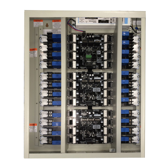
DESCRIPTION The CX Panel is shipped in one package. Panels are configured with all 16 or 24 relays of the same type installed or with space only for relays to be installed in the field. The relays are mounted with lighting circuit terminals in the high voltage area. The low voltage control inputs are located in the low voltage area of the panel. - Page 3 FIGURE 1- CX PANEL INTERIOR Locate the enclosure on the mounting surface and use a level to ensure that it is properly oriented and aligned. Secure the enclosure to the mounting surface with hardware as appropriate for the application using the three keyed mounting holes located near the top corners and in the center bottom of the enclosure as shown below in Figure 2.
-
Page 4: Installing Individual Relay Cards
INSTALLING INDIVIDUAL RELAY CARDS Relay Panels are most commonly shipped with all relay cards installed. If the project requires different types of relays installed in the same panel then the relays are supplied separately and they will require field installation. In this application reference the applicable Relay Installation Instructions supplied with the individual Relay Cards on how to install relays. -
Page 5: Operating The Panel
Low Voltage Control Diagrams shown in Figure 3 below are for use with Hubbell ControlsInput Devices ONLY. Diagrams may not apply to input devices from other manufacturers. FIGURE 3 - LOW VOLTAGE INPUT WIRING DIAGRAMS OPERATING THE PANEL The User Interface control ribbon cable is supplied connected between the User Interface Ribbon Cable Connector on the Mother Board and the User Interface Module that is attached to the panel door. -
Page 6: Troubleshooting
TROUBLESHOOTING A blinking “green” Relay board status LED indicates that communication has not been properly established for this card. Contact Hubbell ControlsTechnical Service at (800) 888-8006 for assistance and replacement as required. A complete Troubleshooting Guide is contained in the “CX Panel User Manual” provided as a downloadable document at www.hubbell-automation.com.
Need help?
Do you have a question about the CX Series and is the answer not in the manual?
Questions and answers