Table of Contents
Advertisement
PRECAUTIONS
•
READ AND FOLLOW ALL SAFETY INSTRUCTIONS.
•
No components in the CX Panel should be removed while power is still being supplied to the CX Transformer. This will result
in Panel failure and the entire CX Panel and components will need to be replaced. This is an unsupported action and voids
Warranty.
•
CAUTION - RISK OF ELECTRICAL SHOCK. To prevent electrical shock, turn off power at the circuit breaker before installing
or servicing unit. Never wire energized electrical components.
•
NOTICE: For installation by a licensed electrician in accordance with National and/or local Electrical Codes and the following
instructions.
•
CAUTION: USE COPPER CONDUCTOR ONLY.
•
Be sure to read and understand all instructions before installing or servicing unit
•
Do not operate unit with panel door assembly or relay guard covers removed.
•
For Indoor use only. Do not use outdoors.
•
Do not mount near gas or electric heaters.
•
Disconnect switch or a circuit breaker must be provided and marked as the disconnecting device.
•
The use of accessory equipment not recommended by the manufacturer may cause an unsafe condition.
•
Confirm that device ratings are suitable for application prior to installation.
•
No user serviceable parts contained inside unit. Refer all service related questions to the factory. All servicing shall be
performed by qualified service personnel.
•
Equipment should be mounted in locations and at heights where it will not readily be subjected to tampering by unauthorized
personnel.
•
Use only approved materials and components (i.e. twist on connectors, electrical box, etc.) as appropriate for installation.
•
NOTICE: Do not install if product appears to be damaged.
•
If the equipment is used in a manner not specified by the manufacturer, the protection provided by the equipment may be
impaired.
•
Do not use this equipment for other than intended use.
SAVE THESE INSTRUCTIONS!
CX Lighting Control Panel
Users' Guide
1
Advertisement
Table of Contents

Related Manuals for HUBBELL LIGHTING CX


Summary of Contents for HUBBELL LIGHTING CX
- Page 1 • No components in the CX Panel should be removed while power is still being supplied to the CX Transformer. This will result in Panel failure and the entire CX Panel and components will need to be replaced. This is an unsupported action and voids Warranty.
-
Page 2: Table Of Contents
Help Screens Controller Version Relay Version Function Keys Reboot System Programming Procedures System Settings Date/Time Preferences Part 3 CX Lighting Control Panels Trouble Shoot- Set Date/Time ing Guide Astro Clock Settings Trouble Shooting Guide Open/Close Times Panel Names After-Hours Sweep... -
Page 3: Part 1 Introduction
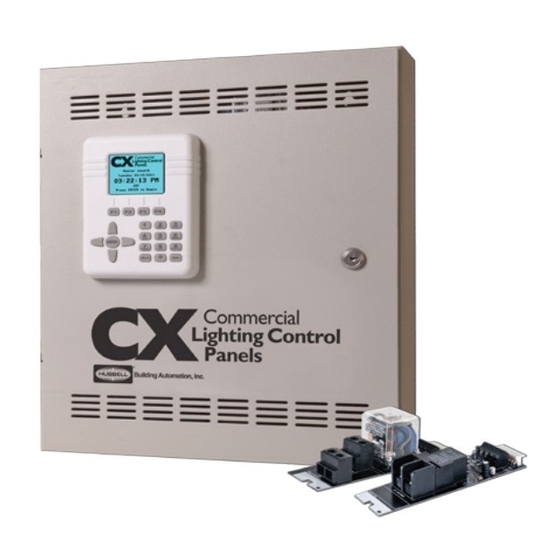
Description CX Commercial Lighting Control Panels – 4, 8, 16 and 24 Relay Panels are shipped in one package. Panels are configured with all relays of the same type installed or no relays with space only for relays to be installed in the field. Relays are mounted with lighting circuit terminals in the high voltage area separated by a metal divider. - Page 4 Enclosure Mounting Typically the CX Panel is installed near the circuit breaker panel or in the ceiling of the room containing the lighting circuits to be controlled. Select an appropriate location that meets the environmental conditions listed in the specification section of this document.
- Page 5 Figure 1(b) – CX16 or 24 Panel Interior Place the enclosure on the mounting surface and use a level to ensure that it is properly oriented and aligned. Secure the enclosure to the mounting surface with hardware as appropriate for the application using the three keyed mounting holes located near the top corners and in the center bottom of the enclosure as shown in Figures 2(a) (b).
- Page 6 Installing Individual Relay Cards CX RELAY PANELS ARE MOST COMMONLY SHIPPED WITH ALL RELAY CARDS INSTALLED. If the project requires different types of relays installed in the same panel then the relays are supplied separately and they will require field installation. In this application, reference the applicable Relay Installation Instruction supplied with the individual Relay Cards on how to install relays.
- Page 7 Notice: Use the Panel Load Schedule Form supplied in the clear plastic pocket inside the Panel Door to record the low voltage input types while making connections. Low Voltage Control Diagrams shown in Figure 3 below are for use with Hubbell Building Automation Input Devices ONLY. Diagrams may not apply to input devices from other manufacturers.
- Page 8 A blinking “green” Relay board status LED indicates that communication has not been properly established for this card. Contact Hubbell Building Automation Technical Service at (888) 698-3242 for assistance and replacement as required. A complete Troubleshooting Guide is contained in the “CX Panel Programming Guide” provided as a separate document with the Panel.
-
Page 9: Part 2 Cx Lighting Control Panels Programming Guide
Special Instructions – Priorities and Masking User interface The user interface is accessed from the front of the CX Panel enclosure and can be operated with the door closed and locked condition. Programming does not require access to the panel interior. All electrical line and low voltage connections should be complete and tested by a qualified electrician prior to programming. - Page 10 HELP Screens The CX Panel system has been designed to include HELP screens throughout the menu structure. Descriptive information is available when a HELP symbol is indicated in the upper right corner of the display, (a question mark in a circle).
- Page 11 Function Keys The F1, F2, F3, and F4 Function Keys located just above the numerical keypad provide additional programming options in various screens. These will appear when additional options are available. Select Screens The following Function Key actions occur in the “Select” screens for Open/Close Times, Groups, Schedules, Holiday Dates, Holiday Schedules, Inputs, Outputs, and Access Control: EXAMPLE - Select Group - Highlight a Group then press ENTER.
-
Page 12: Date/Time Preferences
Programming Procedures When the system is powered on, you will see the CX Lighting Control Home Screen. If the CX Lighting Control Home Screen is not displayed, press ESC several times until it is displayed. Press ENTER to display the MAIN MENU. - Page 13 Edit each field by scrolling RIGHT/LEFT until the desired characteristic appears. Scroll DOWN to the next field and make additional selections as needed. Daylight Savings Time (DST) is default set as ON. Be sure to select the correct Time Zone for your location. WARNING: Astronomical clock and schedule functions will not operate as expected if the correct time zone is not selected.
- Page 14 Open/Close Times TIP: The use of Open/Close Times for scheduling is optional and can be useful in applications where the business operation hours are likely to change periodically and more than one schedule is to be used. Each schedule can be set to reference an Open/Close time rather than having to re-set the discrete times when the schedules need to change.
- Page 15 The Start Time: <Clock> selection will perform sweeps at the selected time 365 days per year. To execute After-Hours Sweeps on selected Days, use the Close Time function. Since Open/Close Times can be developed based on all of the CX Panel Schedules functionality, then Close Time can be any or all days of the week.
- Page 16 “No Blink” function. Idle Time-Out Settings Idle Timeout defines the time after which the CX Controller will log out an inactive user. The system default is “2”. When set as “0” the Idle Timeout is in the “disabled” state.
- Page 17 Clock Adjustment Clock Adjustment allows for the user to adjust the real-time clock to run slower by 0-127 parts per million. The clock cannot be adjusted to run faster than normal. • From the Main Menu, select System Settings > Clock Adjustment. Then press ENTER.
- Page 18 Operational descriptions for a Scenario: Outdoor Scenerios Photocell ON/OFF Automatic photocell ON/OFF control of outdoor lighting Photocell ON/Sched OFF Automatic photocell control ON and schedule control OFF of outdoor lighting Photo ON/Sch OFF/Ovride SW Automatic photocell control ON and schedule control OFF of outdoor lighting with manual switch bypass TIMED-ON control.
- Page 19 Example How Scenarios Work For this exercise we will be demonstrating the Scenario steps to achieve manual ON/ automatic OFF for a room with a motion sensor and a switch. • From the Main Menu, select Scenarios >Factory Defaults. Then press ENTER. •...
- Page 20 There are a total of 32 groups available. Groups that have been programmed will be indicated on the CX User Interface display by a solid box adjacent to the group name. Once a Group has been created and saved, it can be viewed, edited, and deleted.
- Page 21 6. Dimming Mode controls whether dimmers in the group 7. Move the arrow keys left/right while highlighting the Dimming are set to a dimming level when an ON or OFF event Mode to change to ON-only, Off-only or ON+OFF if applicable. occurs, if applicable.
-
Page 22: Schedules - Days Of The Week
When in the <Full Week> selection, scroll down to Days: [CHANGE] to select or deselect days to include in the schedule. When complete use the F1 key to Save changes. CX Programming TIP: ON and Mon-Fri Schedules allow for a single entry of OFF times for weekdays, M-F + Sat adds Saturday to the single entry list (Same ON/OFF for all 6 days). -
Page 23: Standard U.s. Holidays
Holidays The CX Panel Holidays programming allows for the blocking of schedules on designated holiday dates. Additionally, the CX Holiday Schedules function allows for any of four Holiday Schedules to be run on selected Holiday Dates. The following programming functions are available in the Holidays Menu: Standard U.S. -
Page 24: Holiday Dates
When finished, scroll down to highlight [SAVE], and then press ENTER to save your changes. Clear Expired Holidays The CX panel allows for the easy removal of programmed Holiday Dates that have occurred in the past with the “Clear Expired Holidays” function. -
Page 25: Select Inputs - Input Designations And Nam
Any Input, regardless of where it is connected in the panel, can be mapped to any relay or group. The CX Panel system can have a Master Panel of 8, 16, or 24 Relays used individually or connected to a Secondary panel of 8, 16, or 24 Relays. -
Page 26: Input-Type And Function
Input Type and Function CX Panel Input type is assigned in the programming process. Inputs can be selected to be a Switch, Motion Sensor, Photocell, Timed On/Off or Timed-On-Only. From the EDIT INPUT Screen, Scroll to Type: Use right/left arrow keys to select type. -
Page 27: Mapping Input Control And Masking
Mapping Input Control and Masking Any CX Panel input can be mapped to any relay, group or preset. All inputs on a relay are defaulted to control that specific relay with a Momentary NO switch station. All Auxiliary inputs default to un-configured. If a relay space does not have a relay installed, the input will not be available to select. -
Page 28: Inputs-Using Photocells And Photocell Settings
CX Panel Photocells are defined as “Open Loop” sensors. Open Loop sensors operate such that the photo sensor views daylight directly and does not respond to or “see” the electric light that it controls. This means the actual value displayed on the CX Panel User interface AND the ON and OFF set points programmed for the Inputs ARE NOT THE ACTUAL light levels in the space. -
Page 29: Photocell Control With Dimming Functionality
If a Group of relays are to be controlled with the same settings, a single Dimmer and photo sensor may be able to control the entire Group as long as the dimming channel and relay amperage do not exceed the specifications of the CX panel and dimming card. - Page 30 From the Main Menu, select Outputs. Then press the ENTER key. • Select Output – Scroll to an Output to program. Select any of the Outputs available based on the Panels in the CX Panel system. When highlighted, press the ENTER key.
- Page 31 <DIM> - Set the dimming level of a dimmer or group of <PRESET> - Activates another preset to allow more dimmers in response to an On event. actions Level: - The Dimming level to be set in percentage units Only one level of preset changing is allowed. <TOGGLE>...
-
Page 32: Dimming
The purpose of Demand Response is to accept a signal, (contact closure), from a power/Utility company and to translate the signal into dimming all channels of the CX panel to conserve energy consumption. When Demand Response is selected there are two settings to set. - Page 33 Dimmer Inputs These are the Inputs that are located on the Dimmer Card they are designed to function with Zone 5 Switch Stations. These Zone 5 switch stations are connected via a CAT5 cable into an RJ45 connector located on the Dimming Card. Typically ON/OFF or Preset functions will be programmed in the Dimmer Input section.
-
Page 34: System Tools
Power-on Settings - Defines power-on state of dimmers that do not have a photocell configured. Dimmers can be set to zero or maximum level or to the last dimming level when power was removed then re-applied. • Once the POWER-ON SETTINGS is selected, scroll to the Dimmer that will need to change the power–on state and choose the appropriate Function,(F), key button. - Page 35 CX Panel. Logging Feature – As long as a CX Panel has an SD card installed it is logging this file can be read as a text file. This is an automatic feature whenever an SD card is present.
- Page 36 LOW. When the MASTER is in effect, other switches at the lower priorities will not be able to function. When the MASTER switch is turned OFF, its effect is to release the MASTER priority. The CX Panel software will then check to see if there is a previously actuated input that should now control the lighting.
- Page 37 Schedules may also be given differing ON and OFF priorities. Schedules that are assigned priorities MUST have both ON and OFF events. This is required because the higher priority event must be canceled by an opposite event set at priority = LOW in order to be canceled.
- Page 38 Example 4: The project has a fire system that gives the lighting system a dry contact closure when the alarm goes on. This closure is connected to one of the auxiliary inputs on the CX Panel. In an alarm event, all of the emergency lighting is to turn on and remain on regardless of wall switch state or time schedules when an alarm happens.
- Page 39 The first user must always have a Master user level. If the first user is not defined, Access Control will not be used by the CX Controller. A password of 0000 can be entered by simply pressing ENTER at the CX Controller main screen. This can be useful when the 0000 user is set to a View-Only user level.
-
Page 40: Part 3 Cx Lighting Control Panels Trouble Shoot
“Hot Swapping” Hot Swapping is when an individual removes components of the CX Panel with the Main Power On. Items referred to as a CX component: CX Motherboard(s), CX Dimming Card, CX Master/Secondary Card, CX Relays, CX Controller or the Ribbon Cable connecting the Controller to the CX Motherboard. - Page 41 CX Master/Secondary Configurations “I’m unable to see Secondary Panel.” With the Power removed to both panels, remove the CX Controller form the Master Panel and connect it to the Secondary Panel. Remove the Interface card and power up the Secondary Panel.
Need help?
Do you have a question about the CX and is the answer not in the manual?
Questions and answers