Table of Contents
Advertisement
Quick Links
Installation, operating and maintenance instructions
English
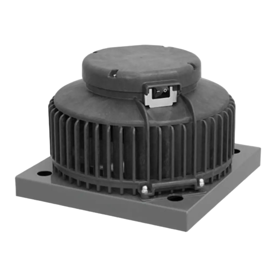
DHA...EC CP 20 / ...EC O CP S
Example configuration shown
CONTENTS
FOREWORD . . . . . . . . . . . . . . . . . . . . . . . . . . . . . . . . . . . . . . . . . . . . . . . . . . . . . . . . . . . . . . . . . . . . . . . . . . . . . . . 2
1.
IMPORTANT INFORMATION . . . . . . . . . . . . . . . . . . . . . . . . . . . . . . . . . . . . . . . . . . . . . . . . . . . . . . . . . . . . . . . . . . 2
2.
GENERAL SAFETY INSTRUCTIONS . . . . . . . . . . . . . . . . . . . . . . . . . . . . . . . . . . . . . . . . . . . . . . . . . . . . . . . . . . . . . 3
3.
ADHERE TO THE FOLLOWING INSTRUCTIONS . . . . . . . . . . . . . . . . . . . . . . . . . . . . . . . . . . . . . . . . . . . . . . . . . . . 6
4.
PRODUCT INFORMATION . . . . . . . . . . . . . . . . . . . . . . . . . . . . . . . . . . . . . . . . . . . . . . . . . . . . . . . . . . . . . . . . . . . . 6
5.
DELIVERY CONTENTS . . . . . . . . . . . . . . . . . . . . . . . . . . . . . . . . . . . . . . . . . . . . . . . . . . . . . . . . . . . . . . . . . . . . . . . 7
6.
TECHNICAL DATA . . . . . . . . . . . . . . . . . . . . . . . . . . . . . . . . . . . . . . . . . . . . . . . . . . . . . . . . . . . . . . . . . . . . . . . . . . . 7
7.
DIMENSIONS . . . . . . . . . . . . . . . . . . . . . . . . . . . . . . . . . . . . . . . . . . . . . . . . . . . . . . . . . . . . . . . . . . . . . . . . . . . . . . 8
8.
TRANSPORT AND STORAGE . . . . . . . . . . . . . . . . . . . . . . . . . . . . . . . . . . . . . . . . . . . . . . . . . . . . . . . . . . . . . . . . . . 8
9.
ASSEMBLY . . . . . . . . . . . . . . . . . . . . . . . . . . . . . . . . . . . . . . . . . . . . . . . . . . . . . . . . . . . . . . . . . . . . . . . . . . . . . . . . 9
10.
ELECTRICAL CONNECTION . . . . . . . . . . . . . . . . . . . . . . . . . . . . . . . . . . . . . . . . . . . . . . . . . . . . . . . . . . . . . . . . . . 13
11.
COMMISSIONING . . . . . . . . . . . . . . . . . . . . . . . . . . . . . . . . . . . . . . . . . . . . . . . . . . . . . . . . . . . . . . . . . . . . . . . . . . 15
12.
OPERATION . . . . . . . . . . . . . . . . . . . . . . . . . . . . . . . . . . . . . . . . . . . . . . . . . . . . . . . . . . . . . . . . . . . . . . . . . . . . . . 15
13.
MAINTENANCE AND CLEANING . . . . . . . . . . . . . . . . . . . . . . . . . . . . . . . . . . . . . . . . . . . . . . . . . . . . . . . . . . . . . . 21
14.
LIFETIME AND DISPOSAL . . . . . . . . . . . . . . . . . . . . . . . . . . . . . . . . . . . . . . . . . . . . . . . . . . . . . . . . . . . . . . . . . . . 22
15.
TROUBLESHOOTING . . . . . . . . . . . . . . . . . . . . . . . . . . . . . . . . . . . . . . . . . . . . . . . . . . . . . . . . . . . . . . . . . . . . . . . 22
16.
ruck Ventilatoren GmbH
Max-Planck-Str. 5
D-97944 Boxberg-Windischbuch
Tel.
+49 7930 9211-300
Fax
+49 7930 9211-166
info@ruck.eu
www.ruck.eu
Roof fan with constant
pressure control
The original instructions were created in the German
Made in EU
2018
language.
Information updated
print 17.11.2022
Subject to change
Advertisement
Table of Contents

Related Manuals for Ruck Ventilatoren DHA EC CP 20 Series


Summary of Contents for Ruck Ventilatoren DHA EC CP 20 Series
-
Page 1: Table Of Contents
TROUBLESHOOTING . . . . . . . . . . . . . . . . . . . . . . . . . . . . . . . . . . . . . . . . . . . . . . . . . . . . . . . . . . . . . . . . . . . . . . . 22 ruck Ventilatoren GmbH Max-Planck-Str. -
Page 2: Foreword
FOREWORD Dear customers, Thank you for choosing our device. Before operating the unit, please read carefully these installation, operating and maintenance instructions. If you have any questions, please contact: (Contact details see page 1) The data provided in these installation, operating and maintenance instructions are for the product description only. A statement about a certain condition or a suitability for a certain application cannot be derived from our information. -
Page 3: General Safety Instructions
2.2. Provisions and regulations When properly installed and operated, the device complies with the applicable standards and EU Directive at the time of its placing on the market. In addition, observe generally valid, legal and other binding regulations of the European or national legislation as well as the regulations in your country for accident prevention and environmental protection. - Page 4 3.1. Intended use Our devices are incomplete machineries as defined in the EU Machinery Directive 2006/42/EC (partly completed ma- chinery). The product is a not ready-for-use machine in terms of the machine directive. It is intended exclusively for installation in a machine or in ventilation equipment and installations or for combination with other components to form a machinery or installation.
- Page 5 Safety sign (warning Consequence triangle) General warning! Indicates possible hazardous situations. Failure to observe the warnings may result in perso- nal injury and / or damage to property. Electricity warning (hazardous voltage)! Indicates possible hazards due to electricity. Failure to observe the warnings may result in death, injury and/or damage to property.
-
Page 6: Adhere To The Following Instructions
ADHERE TO THE FOLLOWING INSTRUCTIONS 4.1. General instructions ■ Persons who assemble, operate, disassemble or maintain our devices must not be under the influence of alcohol, drugs or pharmaceuticals that may affect perception and responsiveness. ■ Responsibilities for the operation, maintenance and regulation of the product should be clearly determined and observed so that there can be no unclear areas of responsibility with regard to safety. -
Page 7: Delivery Contents
5.1. Nameplate ATTENTION! The information on the nameplate must always be observed! Legend: UKCA marking ■ I Max. current consumption CE marking ■ t Max. ambient temperature / Max. medium temperature EAC marking ■ P Rated power consumption Product name ■... -
Page 8: Dimensions
DIMENSIONS DHA...EC CP 20 / ...EC O CP S Product name Item number □321 □245 Ø213 6x M6x15 DHA 190 EC O CP S 01 165071 4xØ9 □321 □245 Ø213 6x M6x15 DHA 220 EC CP 20 129688 4xØ9 □321 □245 Ø213 6x M6x15 DHA 250 EC CP 20... -
Page 9: Assembly
10. ASSEMBLY Assembly work may only be performed by specialist personnel in accordance with the installation and operating ma- nual and the regulations and standards in force. The following points should be noted and followed: ■ The foundation must be even and levelled. It must not exhibit unevenness or a slope in any direction. ■... - Page 10 10.1. Mounting on roof socket (DSF) ■ Fasten the roof fan (2) with screws and washers (3) and (4) on the roof socket (1) 10.2. Mounting of electrical connection Connection power supply: ■ Release screws (1) ■ Remove cover (2) ■...
- Page 11 Dachventilator Roof fan 129688 129688 Tube Rohr Illustrations exemplary Accesorii DVN Intern General tolerances DIN ISO 2 ruck Ventilatoren Max-Planck-Str. 5 53.651 kg Protection Mark according to D-97944 Boxberg 1:22 Do not scale drawing Roof fan Roof fan 129688 129688...
- Page 12 Roof fan 129688 129688 Tube Illustrations exemplary Accesorii DVN_5 Accesorii DVN_5 Intern General tolerances DIN ISO 2 ruck Ventilatoren Intern General tolerances DIN ISO 2768-mK ruck Ventilatoren Max-Planck-Str. 5 62.736 kg Protection Mark according to Max-Planck-Str. 5 62.736 kg Protection Mark according to ISO16016...
-
Page 13: Electrical Connection
11. ELECTRICAL CONNECTION • Electricity warning (hazardous voltage)! » Failure to observe the hazard may result in death, injury or damage to property. → Before performing any work on conductive parts, always disconnect the unit completely from the electri- city supply and make sure that it cannot be switched back on again. The electrical installation may only be carried out by qualified electricians in compliance with the installation, operating and maintenance instructions and the applicable national regulations, standards and guidelines: ■... - Page 14 Only potential-free contacts may be connected at terminals X3 and X4, and X5 and X6. Applying an external voltage can seriously damage the regulator. The regulations for safety extra-low voltages must be observed. The maximum pressure in a ventilation plant must not exceed 5000 Pa. This would result in severe damage to the regulator.
-
Page 15: Commissioning
12. COMMISSIONING Commissioning by trained technical personnel may only be performed after any risk has been ruled out. The following checks should be performed in accordance with the installation and operating manual and the regu- lations in force: ■ Correctly sealed installation of the unit and duct system. ■... - Page 16 13.2. Operation with a control unit (optionally) ATTENTION: When disconnecting the control unit from the unit after programming, the adjusted set- points will be deleted. The manually adjusted setpoints by the rotary switch will then apply. The control unit is used for controlling and entering various functions. The display shows the various operating parame- ters and error messages.
- Page 17 13.2.2. Menu functions Status ON / OFF Press the ON/OFF button (2) to switch the unit on or off. The unit‘s status now appears on the display with the current values. Status display DAY – Changing the setting ...
- Page 18 As bus line is recommended a twisted pair data cable with 120 Ohm impedance. Adresse = 5 Baudrate = 9600 0 = 2400 1 = 4800 2 = 9600 Night ruck Ventilatoren GmbH 136064_00 Sollwert erreicht / Max-Planck-Strasse 5 3 = 14400 CONP 1000Für BDA setpoint reached D-97944 Boxberg...
- Page 19 Function code Name Sub-function Description 08 Hex Return Query Dat Send the received message back 08 Hex Restart Communications Restart communication 08 Hex Force Listen Only Mode Switch to listen-only mode 13.3.4. Parameter table Register Protocol D a t a Autho- Parameter name Value range...
- Page 20 Example for switching on and off: To switch on, 128 (decimal) must be written into register 33 (status and control word). To switch off, 64 (decimal) must be written into register 33 (status and control word). 13.3.5. Current value table Register Protocol D a t a...
-
Page 21: Maintenance And Cleaning
14. MAINTENANCE AND CLEANING Servicing, troubleshooting and cleaning may only be performed by specialised personnel in accordance with this installation and operating manual and the regulations in force. ■ Make sure that no connections or components are loosened unless the device is disconnected from the mains. -
Page 22: Lifetime And Disposal
15. LIFETIME AND DISPOSAL 15.1. Product life The motors are equipped with maintenance-free, permanently lubricated ball bearings. Under normal operating condi- tions, the expected lifetime is about 30,000 operating hours. The information given here depends strongly on the respective field of application as well as the environmental condi- tions. - Page 23 Fault Possible cause Remedy methods ■ Fan does not start ■ No power supply ■ Check mains supply / connections ■ Impeller does not rotate freely ■ Find out the causes and, if possible, remove the fault. If not possible, contact the supplier. ■...
- Page 24 Ventilatoren GmbH Max-Planck-Str. 5 D-97944 Boxberg-Windischbuch Tel. +49 7930 9211-300 +49 7930 9211-166 info@ruck.eu www.ruck.eu Information updated print 17.11.2022 mdar_pb_16d_k10001_en We reserve the right to make changes Language: English...
Need help?
Do you have a question about the DHA EC CP 20 Series and is the answer not in the manual?
Questions and answers