Table of Contents
Advertisement
Available languages
Available languages
Quick Links
Advertisement
Chapters
Table of Contents

Subscribe to Our Youtube Channel
Related Manuals for KNOVA KN DP-3000N


Summary of Contents for KNOVA KN DP-3000N
- Page 1 ” Variable speed drill press Taladro de banco, velocidad variable We invite you to read the user manual before operating your equipment. Lo invitamos a leer el manual del KN DP-3000N usuario antes de operar su equipo.
-
Page 2: Table Of Contents
INTRODUCTION Thanks for purchasing the KNOVA Drill Press. We know you are excited to put your tool to work, but first, please take a moment to read through the manual. Safe operation of this tool requires that you read and understand this operator’s manual and all the labels affixed to the tool. -
Page 3: General Safety Rules
GENERAL SAFETY RULES 6. If operating a power tool in a damp location is tools. Such preventive safety measures reduce the risk of unavoidable, use a ground fault circuit interrupter (GFCI) starting the power tool accidentally. protected supply. Use of a GFCI reduces the risk of 4. -
Page 4: Electrical Information
SPECIFIC RULES FOR THE DRILL PRESS 6. DRILLING ACCESSORIES. 13. Do not touch moving pieces. Keep hands away from the drill bit during operation. If cleaning is necessary, turn • Make sure the drill bit is not damaged before use; only off the machine and use a brush to remove sawdust and use undamaged drill bits chips instead of your hands. -
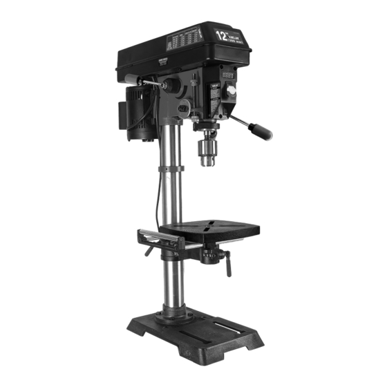
Page 5: Know Your Drill Press
18. LED worklight switch 19. Extension wing with integrated rollers 20. Support lock handle 21. Speed control handle Various drill bits, 22. Power cord vises, clamps and other accessories Fig. 2 23. Chuck key storage can be purchased from www.knova.com.mx... -
Page 6: Assembly And Adjustments
Check your packing list against the diagram below. If any part is damaged or missing, please contact our customer service at 55 5272 4808, M-F 8-5 CST or e-mail us at centrodeservicio@knova.com.mx and DO NOT plug the drill press in or turn ON. - Page 7 ASSEMBLY AND ADJUSTMENTS DRILL PRESS HEAD TO COLUMN (FIG. 5) WARNING If any part is missing or damaged, do not plug the drill press in until the missing or damaged WARNING The drill press head is heavy. To avoid part is repaired or replaced. injury, two people should lift it into position.
- Page 8 ASSEMBLY AND ADJUSTMENTS SPEED HANDLE (FIG. 7) 2. Open the chuck jaws (Fig. 9 - 3) by manually turning the chuck barrel clockwise. Make sure the jaws are 1. Insert the speed handle (Fig. 7 - 1) into the threaded completely recessed inside the chuck.
- Page 9 ASSEMBLY AND ADJUSTMENTS RAISE OR LOWER THE TABLE (FIG. 11) INSTALLING A DRILL BIT (FIG. 13) 1. Loosen the support lock handle (Fig. 11 - 1) and turn 1. Place the chuck key (Fig. 13 - 1) into the side keyhole of the crank handle (Fig.
- Page 10 ASSEMBLY AND ADJUSTMENTS ADJUSTING THE LASER (FIG. 15 & 16) 4. While firmly holding the spring housing (Fig. 17 - 3), carefully pull spring housing out until it clears the raised WARNING stop (Fig. 17 - 4). Do not stare directly at the laser beam. Observe all safety rules.
-
Page 11: Operation
ASSEMBLY AND ADJUSTMENTS LIGHT & LASER LINE ON/OFF SWITCHES (FIG. 19) POSITION THE TABLE AND WORKPIECE (FIG. 20) The light switch (Fig. 19 - 3) Always place a piece of backup material (Fig. 20 - 1) is located on the lamp cover. (wood, plywood, etc.) on the table underneath the workpiece The laser switch (Fig. - Page 12 OPERATION • All metal workpieces should be clamped down securely. Any tilting, twisting, or shifting causes a rough drill hole, and increases the potential of drill bit breakage. • Never hold a metal workpiece with your bare hands. The cutting edge of the drill bit may seize the workpiece and throw it, causing serious injury.
-
Page 13: Maintenance
OPERATION DRILL BIT SIZE RECOMMENDATIONS R P M Woo d A l um inum, Zinc, Brass Iron, St e el 2000 to 3200 3/8 in. 9.5 mm 7/32 in. 5.6 mm 3/32 in. 2.4 mm 1400 to 2000 5/8 in. 16 mm 11/32 in. -
Page 14: Troubleshooting
Stop using the tool immediately if any of the following problems occur. Repairs and replacements should only be performed by an authorized technician. For any questions, please contact our customer service at 01 800 70 56682 ó 55 5272 4808, M-F 8-5 CST or e-mail us at centrodeservicio@knova.com.mx PROBLEM... -
Page 15: Parts List (Assembly)
PARTS LIST (ASSEMBLY) NOTE: Parts may only be available in their respective subassemblies. Not all parts may be available for purchase. PART NO . D E S CRI PTI O N Q T Y PART NO. DESCRIPTI ON Q TY A - S P IND LE P UL L EY AS SE M BLY ( PA RT 4214B -A A ) G - CRAN K ASSEMBLY (PART 4214B-A G) 4214B-002... -
Page 16: Parts List (Pieces)
PARTS LIST (PIECES) N O. PART NO . D ES CR IPT IO N Q TY PART NO. DESCRI PTI ON Q TY 4214B-001 Circlip for shaft, Ø24 4214B-079 Screw M6 x 8 4214B-006 Cogged V-belt, 10 x 900 4214B-080 Pin 4214B-019 Lock nut, M10 Phillips-head screw, M5 x 8, 4214B-081... -
Page 17: Exploded View
EXPLODED VIEW KN AP-3000N ” Variable speed drill press Taladro de banco, velocidad variable... - Page 18 INTRODUCCIÓN Gracias por comprar el taladro de columna KNOVA. Sabemos que está emocionado de poner su herramienta a trabajar, pero primero, tómese un momento para leer el manual. La operación segura de esta herramienta requiere que lea y comprenda este manual del operador y todas las etiquetas adheridas a la herramienta.
-
Page 19: Reglas Generales De Seguridad
REGLAS GENERALES DE SEGURIDAD 4. No abuses del cable. Nunca utilice el cable para 3. Desconecte el enchufe de la fuente de alimentación y/o transportar, tirar o desenchufar la herramienta eléctrica. el paquete de baterías de la herramienta eléctrica antes Mantenga el cable alejado del calor, el aceite, los bordes de realizar ajustes, cambiar accesorios o almacenar afilados o las piezas móviles. - Page 20 REGLAS ESPECÍFICAS PARA EL TALADRO DE PRENSA 10. No opere esta herramienta hasta que esté completamente ADVERTENCIA No permita que la comodidad o la ensamblada e instalada de acuerdo con las instrucciones. familiaridad con el producto reemplacen el estricto cumplimiento de las normas de seguridad del producto. 11.
-
Page 21: Información Eléctrica
INFORMACIÓN ELÉCTRICA INSTRUCCIONES DE PUESTA A TIERRA DIRECTRICES Y RECOMENDACIONES PARA EXTENSIONES En caso de mal funcionamiento o avería, la conexión a tierra proporciona la vía de menor resistencia para la corriente Cuando use un cable de extensión, asegúrese de usar uno eléctrica y reduce el riesgo de descarga eléctrica. -
Page 22: Conozca Su Taladro De Prensa
55 5272 4808, lunes a viernes de 9:30-5:30 o envíenos un correo electrónico a LIMPIEZA DE LA SUPERFICIE DE LA MESA DE TRABAJO centrodeservicio@knova.com.mx y NO enchufe ni encienda el Su taladradora viene protegida con una capa de revestimiento taladro de columna. - Page 23 MONTAJE Y AJUSTES 1. Conjunto cabezal/motor 7. Ala de extensión 12. Manivela de mesa con rodillos integrados 2. Montaje de columna 13. Llaves hexagonales (3 mm y 4 mm) 8. Llave de mandril 3. Mesa 14. Asas de alimentación (3) 9.
- Page 24 MONTAJE Y AJUSTES SOPORTE DE SOPORTE DE MESA A MESA (FIG. 4) MANIJAS DE ALIMENTACIÓN (FIG. 6) 1. Coloque la manivela (Fig. 4 - 1) en el eje (Fig. 4 - 2) del 1. Inserte las tres manijas de alimentación (Fig. 6 - 1) en las soporte de la mesa de modo que la parte plana del eje aberturas roscadas en el cubo de alimentación (Fig.
- Page 25 MONTAJE Y AJUSTES QUITE EL MANDRIL (FIG. 10) 1. Gire las manijas de alimentación (1) para bajar el mandril (2) a la posición más baja. 2. Inserte la llave de deriva (3) en la abertura de la pluma. Golpee suavemente la cuña con un mazo de goma (4) (no incluido).
- Page 26 MONTAJE Y AJUSTES AJUSTAR LA MESA PARA QUE MESA DE ESCUADRADO A LA BROCA (FIG. 14) SEA HORIZONTAL (FIG. 12A) 1. Inserte una broca de 3” de largo (Fig. 14 - 1) en el mandril 1. Afloje el perno de bloqueo (Fig.
- Page 27 MONTAJE Y AJUSTES 4. Si es necesario ajustar el láser: “JUEGO” ANGULAR DEL HUSILLO (FIG. 18) a. Con la llave hexagonal de 3 mm incluida, gire Mueva el eje a la posición más baja hacia abajo y manténgalo los tornillos de ajuste del láser (Fig. 15 - 3) en sentido en su lugar.
-
Page 28: Operación
MONTAJE Y AJUSTES COLOQUE LA MESA Y LA PIEZA DE TRABAJO (FIG. 20) Coloque siempre una pieza de material de respaldo (Fig. 20 - 1) (madera, madera contrachapada, etc.) sobre la mesa debajo de la pieza de trabajo (Fig. 20 - 2). Esto evitará que se astille la parte inferior de la pieza de trabajo cuando la broca se rompa. - Page 29 OPERACIÓN • Todas las piezas de trabajo de metal deben sujetarse firmemente. Cualquier inclinación, torsión o desplazamiento provoca un orificio de perforación áspero y aumenta el potencial de rotura de la broca. • Nunca sostenga una pieza de trabajo de metal con las manos desnudas.
-
Page 30: Mantenimiento
OPERACIÓN RECOMENDACIONES DE TAMAÑO DE BROCA RP M Ma de r a Al um ini o, Zinc, Latón Hierro, Acer o 2000 a 3200 3/8” 9.5 mm 7/32” 5.6 mm 3/32” 2.4 mm 1400 a 2000 5/8” 16 mm 11/32” 8.75 mm 5/32”... -
Page 31: Solución De Problemas
Las reparaciones y sustituciones solo deben ser realizadas por un técnico autorizado. Para cualquier consulta, comunícate con nuestro servicio de atención al cliente al 01 800 70 56682 ó 55 5272 4808, L-V 8-5 CST o escríbenos a centrodeservicio@knova.com.mx PROBLEMA CAUSA SOLUCIÓN... -
Page 32: Lista De Partes (Conjunto)
SOLUCIÓN DE PROBLEMAS PROBLEMA CAUSA SOLUCIÓN El motor 1) Interruptor defectuoso o roto 1) Comuníquese con atención al cliente al 01 800 70 56682. no funcionará 2) Cable de alimentación defectuoso 2) Comuníquese con atención al cliente al 01 800 70 56682. o dañado 3) Comuníquese con atención al cliente al 01 800 70 56682. -
Page 33: Lista De Partes (Piezas)
LISTA DE PARTES (CONJUNTOS) NO. DE PARTE DESCRIPCI ÓN CANT. N O. N O. D E PART E DE S CRI PCIÓ N CANT. G - CO NJ UNTO D EL M AN I V EL A ( PA RT E 4214B- A G ) N - CONJUNTO DEL COLLAR DE LA ESCALA (PART E 4214B -A N) 4214B-129 Mango... - Page 34 LISTA DE PARTES (PIEZAS) N O. N O . DE PA RTE D E SCR I PCI Ó N CANT. NO. DE PARTE DESCRI PCI ÓN CANT. 4214B-077 Tornillo de cabeza Phillips, M5 x 10 113 4214B-113 Resorte de compresión del motor 4214B-078 Broche de llave 114 4214B-114 Base de resorte 4214B-079 Tornillo M6 x 8...
- Page 35 DIAGRAMA DE ENSAMBLADO KN AP-3000N ” Variable speed drill press Taladro de banco, velocidad variable...
- Page 36 www.knova.com.mx...
Need help?
Do you have a question about the KN DP-3000N and is the answer not in the manual?
Questions and answers