Advertisement
Quick Links
Advertisement

Subscribe to Our Youtube Channel
Related Manuals for Scame BE-D Series

Summary of Contents for Scame BE-D Series
- Page 1 BE-D Series User Manual...
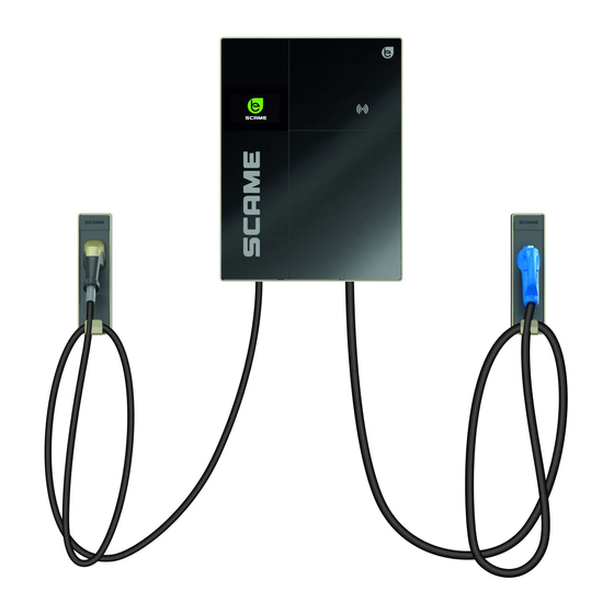
- Page 2 DISPOSAL INSTRUCTIONS INTRODUCTION Scame BE-D wallbox is a wall-mounted DC charger designed for Battery Electric Vehicles (BEVs) and Plugin Hybrid Electric Vehicles (PHEVs). It is compatible with either CCS type 2, or CHAdeMO, or both charging methods depending on the configuration of choice.
- Page 3 BE-D wallbox should be installed, operated, serviced, and maintained only by qualified personnel. No responsibility is assumed by SCAME PARRE S.p.A. for any consequences caused by improper use of this material. The technical documentation is an integral part of this product. Always keep it at hand until the unit reaches its end of life, as it provides important information.
- Page 4 In this case the RFID card reader is enabled and the unit is setup in such a way as to grant permission to charge only to users holding previously authorized RFID cards. The registration of authorized user cards is done directly at the charger level via the Scame Management System. To configure this Mode click on the “change mode” interface button.
- Page 5 And then confirm passage to “Net” Image 3 Once the station has been set to work in “NET” mode, the administrator can then add new user cards. To add new cards select “Cards” in the menu and click on “Add Card” button on the interface. Image 4 Authorization via OCPP central station (Net OCPP) It is possible to configure the station so that it is monitored and controlled by a central station via OCPP 1.6 JSON...
- Page 6 BE-D SERIES enter into “Settings” in the menu and then select “Operating mode”. Once selected, in the interface change Settings.logic.systemLogic from “Local” to “OCPP1.6 JSON” and fill in the required configuration parameters (these parameters must be supplied by the EMSP).
- Page 7 such a way as to clearly show that the charging infrastructure is up and running, without unnecessarily shining excessive light at the user’s eyes. This strategy maximizes the display lifespan while saving electric energy. At a distance of approximately half a meter the motion sensor detects that an end user is approaching. This causes the charger to exit its default non-operational state and enter the operational mode.
-
Page 8: Charging Process
BE-D SERIES CHARGING PROCESS While being in the default non-operational state BE-D wallbox shows the “be logo” on the TFT display. Image 8: be logo screensaver By either triggering the motion sensor or by tapping on the TFT display the charger enters the operational mode and the display shows the connectors selection screen. - Page 9 shows the language selection screen, among with the supported languages. Image 10: RFID reader display screen Image 11: Languages Image 12: Preparing CHAdeMO - connector unplugged...
- Page 10 BE-D SERIES Image 13: charging operations Image 14: Preparing CHAdeMO - connector plugged in With most electric vehicles the charge process will proceed automatically from this point on. Instead, with older CHAdeMO EVs supporting only the first release of the protocol, i.e. CHAdeMO version 0.9.1, the plug presence into the EV inlet can not be automatically detected.
- Page 11 Image 15: confirm CHAdeMO At this point the data link between the EV and the charger established and, after a few seconds of communication, the transfer of electric energy begins. Image 16 exemplifies the informative data being shown to the user, which include the status of the plug (reserved, charge in progress, charge completed), the State of Charge of the battery reported by the EV (SoC 0 to 100%), the amount of energy already delivered to the EV (kWh), the instantaneous power (kW), the time the charging started, and its duration (h:min).
- Page 12 BE-D SERIES Image 17: detail 1 Image 18: detail 2 Image 19: error message Should any error or fault occur during charging, a message similar to the one shown by image 19 will be posted.
- Page 13 Image 20: confirm stop The charging process will stop either automatically, when the EV reaches the preset SoC previously decided by the end user, or manually, if the end user so decides. In the second case a dedicated push button needs to be presses to confirm the decision.
- Page 14 BE-D SERIES CONNECTIVITY Every single model supports a standard wired Ethernet connection And comes with a built-in wireless router that provides mobile 4G(LTE)/3G/2G and WiFi connectivity as well. For mobile 4G(LTE)/3G/2G communication a SIM card needs to be inserted into the router. See image 22.
- Page 15 PRODUCT SPECIFICATIONS, STANDARDS AND REGULATIONS General Information SCAME DC WALLBOX, 25 kW, CE, 1 or 2 output connectors, CCS type 2 and CHAdeMO, 4.5 m cables, 7” TFT touch Description display, RFID reader, EMC Class A Technical Data Configuration 3 (206.D91-E12): Configuration 1 (206.D91-E10):...
- Page 16 BE-D SERIES CE conformity marking with the relevant EU directives: 2014/35/EU, Low Voltage Directive (LVD for Safety) 2014/30/EU, Electro-Magnetic Compatibility (EMC) 2014/53/EU, Radio Equipment Directive (RED) pending 2011/65/EU (RoHS2) EMC Emission: Class A, IEC 61000-6-4, EMC Immunity: IEC 61000-6-2 industrial environments...
-
Page 17: Maintenance
WARRANTY THIS LIMITED WARRANTY IS EXPRESSLY LIMITED TO THE ORIGINAL PURCHASER (“PURCHASER”) OF THE BE-D SCAME Charger (“CHARGING STATION”). DISPOSAL INSTRUCTIONS “Implementation of Directive 2012/19/EU on Waste Electrical and Electronic Equipment (WEEE)”, pertaining to reduced use of hazardous substances in electrical and electronic... - Page 18 BE-D SERIES...
- Page 20 VIA SPIAZZI, 45 24028 PONTE NOSSA (BG) ITALIA TEL. +39 035 705000 FAX +39 035 703122 emobility-scame.com e-mobility@scame.com e-mobility@scame.com...
Need help?
Do you have a question about the BE-D Series and is the answer not in the manual?
Questions and answers