Advertisement
Quick Links
No: 341169 1/20
Catalog Number(s) • Numéro(s) de Catalogue • Les Numéros de Catalogue: RRW600V, RRW600VV2
Country of Origin: Made in China • Pays d'origine: Fabriqué en Chine • País de origen: Hecho en China
READ AND SAVE THESE INSTRUCTIONS
To be installed by a certified electrician or other qualified person.
WARNING – To prevent severe shock or electrocution, always turn
poweroff at the service panel before installing this product, working on the
circuit, or changing a lamp.
CAUTION
• Do not connect this product to a power source other than 120VAC,
60Hz.
• Use copper wire only.
Specifications
Load.......................................... Single Pole or 3 Way
Time Delay ............................... 30 Seconds to 30 Minutes
Environment ............................. Indoor Use Only
Tools Needed
Insulated Screwdriver, Wire Strippers
RRW600V
DESCRIPTION AND OPERATION
The RRW600V vacancy sensor is designed to replace a standard light
or fan switch and are suitable for use in new construction or retrofit/
replacement applications. The sensor uses passive infrared technology
to sense human motion in a space and turn the light OFF when the room
is vacant. It is ideal for applications in a home where there is a direct line
of sight from the sensor to the room, including bedrooms and family/living
rooms.
Vacancy Mode:
In this mode, the load is required to be turned ON manually, and will
turn OFF at the desired time delay, if no motion is detected. If motion is
detected within 30 seconds after it automatically turns OFF, the RRW600V
automatically turns the load back ON.
INDICATOR LED
The RRW600V has an onboard indicator LED located at the top of the
unit. This indicator is used to show when motion is detected. The LED
is also used while programming the RRW600V and indicates STATUS
during power up. The LED is further used to indicate a malfunctioning unit.
Vacancy mode can be programmed/selected to function with or without the
LED indicator if preferred by the user. The LED can be enabled / disabled by
pressing and holding the On/Off button for 25s.
LED – locator light will be in an "On State" when the load is off and will blink
when motion is detected;
LED – locator light will be in an "Off State" when the load is on and will blink
when motion is detected
LED – flashes quickly two times ON per 2.5s, if the unit is PIR
malfunctioning.
Table 1
Setting
Status
From User
LED or LOAD State
(Input to the device)
(Acknowledgement
from the device)
With the load ON or OFF,
LED will blink 5 times
hold down the ON/OFF
and then turn off
Initiate
button for 10 seconds
then release
Push down the ON /OFF
LED flashes quickly two
Time Delay
button first time
times per 1.5s.
Adjustment
Push down the ON /OFF
LED flashes quickly
Mode – To
button second time
three times per 1.5s.
change the
amount of time
Push down the ON /OFF
LED flashes quickly four
Activate
before the
button third time
times per 1.5s.
sensor switch
Push down the ON /OFF
LED flashes quickly five
turns off after
button fourth time
times ON per 1.5s.
last movement
Push down the ON /OFF
LED flashes quickly one
button fifth time
time per 1.5s.
Hold down the ON /OFF
LED will blink 5 times
Save / Exit
button for 10 seconds
and then turn off
then release
Table 2
LED or LOAD State
From User
Setting
Status
(Acknow ledgement
(Input to the device)
from the device)
When the
With the load ON or
LED will blink 5 times
LED is
OFF, hold down the
and then turn off
Enabled
ON/OFF button for
25 seconds
Enable and
disable the
status LED
When the
With the load ON or
LED will blink 5 times
indicator
LED is
OFF, hold down the
and then turn off
Disabled
ON/OFF button for
25 seconds
COVERAGE AREA
The RRW600V has a maximum coverage range of 180 degrees and a
coverage area of 600 square feet (56 square meters). The sensor must
have a clear and unobstructed view of the coverage area. Objects blocking
the sensor's lens may prevent detection thereby causing the light to turn off
even though someone is in the area.
Windows, glass doors, and other
transparent barriers will obstruct the
sensor's view and prevent detection.
Figure 1: Sensor Coverage Area
Figure 1 : Zone de portée du détecteur
Figura 1: Área de cobertura del sensor
1. Prepare the switch box.
After the power is turned off at the circuit breaker box, remove the existing wall
plate and mounting screws. Pull the old switch out from the wall box.
2. Identify the type of circuit.
Single Pole
In a Single Pole Circuit (see Figure
2), two single wires connect to two
screws on the existing switch. A
ground wire may also be present
and connected to a ground terminal
on the old switch.
3-Way
In a 3-way circuit (see Figure 3),
there will be [2 runners and
1 common] for both switches
involved.
Result
Figure 3: 3-Way
Figure 3: Trois voies
Figura 3: 3 Vías
Enters
Time Delay
Adjustment Mode
CAUTION For your safety: Connecting a proper ground to the sensor provides
protection against electrical shock in the event of certain fault conditions. If
Set the time delay to
a proper ground is not available, consult with a qualified electrician before
5 Minutes
continuing installation.
Set the time delay to
3. Prepare the Wires.
10 Minutes
Tag the wires currently connected to
Set the time delay to
the existing switch, so that they can be
15 Minutes
identified later. Disconnect the wires. Make
Set the time delay to
sure the insulation is stripped off the wires
30 Minutes
to expose their copper cores to the length
Set the time delay
indicated by the "Strip Gage," in Figure 3a.
to 30 Seconds
4. Wire the sensor.
Save / Exit Time
1-pole configuration:
Delay Adjustment
Twist existing wires together
Mode
with the wire leads on the
RRW600V sensor as indicated
below. Cap them securely using
the wire nuts provided. See
Result
Figure 4.
• Connect the green or non-
LED will Disable: locator light
insulated (copper) GROUND
will be in an "On State" when
wire from the circuit to the
the load is off and will not blink
green ground terminal on the
when motion is detected; the
RRW600V. Make sure there
locator light will be in an "Off
is a solid ground connection.
State" when the load is on and
will not blink when motion is
• If neutral is available in the
detected
box, connect to the Blue and
White striped (signal) wire on
LED will Enable: locator light
the RRW600V. In cases of
will be in an "On State" when
the load is off and will not blink
retrofit or replacement where
when motion is detected; the
no neutral is present, connect the signal wire to ground.
locator light will be in an "Off
• Connect the power wire from the circuit (HOT) to the black wire on the
State" when the load is on
RRW600V.
and will blink when motion is
• Connect the power wire to the lamp or fan (LOAD) to the red wire on the
detected.
RRW600V.
Multilocation configuration (using existing companion 3-way switch):
see Figure 5.
• Connect the green or non-insulated (copper) GROUND wire from the circuit
to the green ground terminal on the RRW600V. Make sure there is a solid
ground connection.
• If neutral is available in the box, connect to the Blue and White striped
(signal) wire on the RRW600V. In cases of retrofit or replacement where no
neutral is present, connect the signal wire to ground.
• Connect the power wire from the circuit (HOT) to the black wire on
the RRW600V.
• Connect the power wire to the lamp or fan (LOAD) to the red wire on
the RRW600V.
• Connect one of the runner wires to the yellow wire of the RRW600V.
• For the companion switch, connect the chosen runner wire (presently
hooked up to the yellow wire of the RRW600V) to the common of the 3-way
25'
companion mechanical switch.
(7.6m)
• Connect one of the poles of the companion 3-way switch to ground.
• For the remaining pole of the companion 3-way switch, do not connect to
anything, but still cap off with a wire nut.
Neutral
12'
Neutre
(3.7m)
Neutro
Line
Black
Ligne
Noir
Linea
Negro
Blue w / White Stripes
Neutral or Ground (See Instructions)
Ground
Green
Terre
Vert
Tierra
Verde
Figure 5: 3-Way Configuration / Figure 5 : Configuration à 3 voies
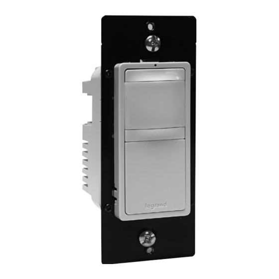
Pass & Seymour
Vacancy Sensor Switch
Interrupteur détecteur d'inoccupation
Interruptor con sensor de "habitación vacía"
Incandescent/ELV: 600W ; CFL/LED: 450W/3.75A; MLV: 600VA; ELV: 5A; Motor: 1/6 hp
Installation Instructions • Notice d'Installation • Instrucciones de Instalación
LIRE ET CONSERVER CES INSTRUCTIONS
Doit être installé par un électricien certifié ou une autre personne qualifiée.
AVERTISSEMENT – Pour éviter tout choc électrique ou une électrocution,
toujours couper l'électricité au niveau du panneau d'alimentation avant
d'installer cette unité, de travailler sur le circuit électrique ou de changer
une lampe.
AVERTISSEMENT
• Ne brancher ce produit qu'à une source d'alimentation de 120 V c.a.,
60 Hz.
• N'utiliser que des fils en cuivre.
Spécifications
Charge ...................................... Unipolaire ou à 3 voies
Temporisation ........................... 30 secondes à 30 minutes
Environnement ......................... Utilisation en intérieur uniquement
Outils nécessaires
Tournevis isolé, dénudeurs de fil
INSTALLATION & WIRING
Figure 2:
Single Pole
Figure 2: Pôle simple
Figura 2: Polo único
3-Way
In a 3-Way circuit, identify the Common/
Hot wire – connected to the terminal
marked Common or the odd-colored
terminal screw.
Trois voies (3-Way)
Pour un circuit à trois voies, identifier le
câble de commun/courant raccordé à la
borne marquée « Commun » ou à la vis
de borne de couleur différente.
3 vías
En un circuito de 3 vías, identifique el
cable Común/Vivo: conectado al terminal
marcado como Común o al tornillo del
terminal de color diferente.
Strip Gauge,
Borne à vis
Traseros para cables
Strip Gage
1/2"
12.7mm
Figure 3a: Wire Stripping
Figure 3a : Dénudage des fils
Figura 3a: Pelado de cables
Neutral
Neutre
Neutro
Load
Charge
Carga
Line
Ligne
Linea
Black / Noir / Negro
NC
Yellow / Jaune / Amarillo
Red
Blue w / White Stripes
Rouge
Rojo
Neutral or Ground (See Instructions)
Ground
Green / Vert / Verde
Terre
Tierra
Figure 4: Single Pole Configuration
Figure 4 : Configuration unipolaire
Figura 4: Configuración del polo único
Load
Charge
Carga
Red
Rouge
H1
common
Rojo
commun
común
H2
Yellow
Jaune
Amarillo
Figura 5: Configuración de 3 vías
®
LEA Y CONSERVE ESTAS INSTRUCCIONES
Para ser instalado por un electricista certificado o persona competente.
ADVERTENCIA – Para evitar descargas eléctricas serias o electrocución,
antes de instalar, trabajar en el circuito o cambiar una lámpara de este
atenuador apague siempre el suministro eléctrico en el panel de servicio.
PRECAUCIÓN
• No conecte este producto a una fuente de alimentación que no sea de
120 V AC, 60Hz.
• Use solamente cables de cobre.
Especificaciones
Carga ........................................ Polo único o de 3 vías
Tiempo de demora ................... 30 segundos a 30 minutos
Entorno ..................................... Solo uso en interiores
Herramientas necesarias
Destornillador aislado, pelacables
Multilocation configuration (using up to 5 units, maximum wire length of
100 ft between companion unit and unit connected to the load):
see Figure 6.
• Connect the green or non-insulated (copper) GROUND wire from the circuit to
the green ground terminal on the RRW600V. Make sure there is a solid ground
connection.
• If neutral is available in the box, connect to the Blue and White striped (signal)
wire on the RRW600V. In cases of retrofit or replacement where no neutral is
present, connect the signal wire to ground.
• Connect the power wire from the circuit (HOT) to the black wire on
the RRW600V.
• Connect the power wire to the lamp or fan (LOAD) to the red wire on
the RRW600V.
• Connect one of the runner wires to the yellow wire of the RRW600V.
• For the companion RRW600V, connect the chosen runner wire (presently
hooked up to the yellow wire of the 1st RRW600V) to the yellow wire of the
companion RRW600V.
• Repeat for additional RRW600V units.
Neutral
Neutre
Neutro
Line
Black
Red
Line
Ligne
Noir
Rouge
Ligne
Linea
Negro
Rojo
Linea
Blue w/White Stripes
Neutral or Ground (See Instructions)
Ground
Green
Ground
Terre
Vert
Terre
Tierra
Verde
Tierra
Figure 6: Multilocation Configuration
Figure 6 : Configuration à plusieurs emplacements
Figura 6: Configuración de ubicación múltiple
5. Put the RRW600V in the wall box. Position the lens above the ON/OFF
button (lens at top, button at bottom). Secure it to the wall box with the
screws provided.
6. Make any necessary adjustments. See the SENSOR ADJUSTMENT section
for information.
7. Attach the new cover plate.
8. Restore power to the circuit. Turn on the breaker or replace the fuse.
INITIAL POWER UP DELAY
There is an initial warm-up (about 1 minute) and calibration period the first
time power is applied to the unit and after the load is replaced. The warm-up
sequence also occurs as a result of a power failure, and any time power to the
unit is cycled.
CHANGING THE COLOR OF THE UNIT
1. Remove the wallplate.
2. Firmly grasp the edges of
the front cover directly below
the lens where it says "open."
Push in one side first until it
pops out, then the other side.
Remove front cover from the unit
(see Figure 7).
3. Take the new color front cover,
place the top peg in first then
snap in each side one at a
time (see Figure 9).
Figura 9: Reemplace la cubierta frontal
TROUBLESHOOTING
Status LED is enabled but not blinking and the load will not turn ON:
• Check the circuit breaker to be sure it is functioning.
• Check to make sure that the device is properly grounded. This device will not
function if it is not grounded.
Load will not turn ON:
Press ON/OFF button. The load should turn ON. If not:
• Check the light bulb and/or motor switch on the fan mechanism.
• Turn OFF power to the circuit then check wire connections.
• For further assistance call 800.223.4185 for technical support.
Load will not turn OFF:
Note: The time delay can be set from 30 seconds to 30 minutes. Ensure that
the time delay is set to the desired delay and that there is no movement within
the sensor's view for that time period.
• To quickly test the unit for proper operation, turn the time delay to minimum
and move out of the sensor's view. Lights should turn off after
30 seconds.
• Press the ON/OFF button. If load does not turn off, turn off power to the
circuit then check wire connections.
• For further assistance call 800.223.4185 for technical support.
NC
Load
Charge
Carga
Line
Black
Ligne
Noir
NC
Linea
Negro
Red
Yellow / Jaune / Amarillo
Rouge
Rojo
Blue w/White Stripes
Neutral or Ground (See Instructions)
Green
Vert
Verde
Tim
e
Mot
Del
OFF
ion
Blin
ay
30m
in.
k
20m
in.
30s
5mi
ec.
10m
in.
n.
Figure 9: Replace Front Cover
Figure 9 : Remplacement de
la protection avant
Advertisement

Related Manuals for LEGRAND Pass & Seymour RRW600V


Summary of Contents for LEGRAND Pass & Seymour RRW600V
- Page 1 Pass & Seymour ® Vacancy Sensor Switch Interrupteur détecteur d’inoccupation Interruptor con sensor de “habitación vacía” Incandescent/ELV: 600W ; CFL/LED: 450W/3.75A; MLV: 600VA; ELV: 5A; Motor: 1/6 hp No: 341169 1/20 Installation Instructions • Notice d’Installation • Instrucciones de Instalación Catalog Number(s) •...
- Page 2 Pass & Seymour/Legrand for consequential damages arising out of, or in connection with, the Pass & Seymour/Legrand en cas de dommage par découlant de ou lié à l’utilisation ou aux responsabilidades por parte de Pass & Seymour/Legrand por daños consecuentes que deriven use or performance of this product or other indirect damages with respect to loss of property, performances de ce produit ou de tout autre dommage indirect lié...