
Related Manuals for Niveo NGSME48T4H


Summary of Contents for Niveo NGSME48T4H
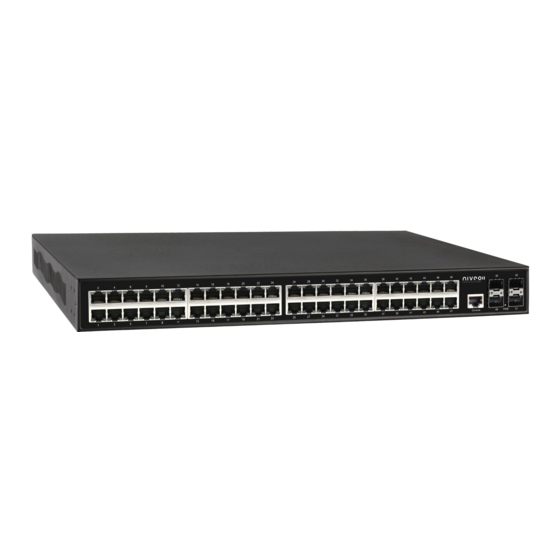
- Page 1 NGSME48T4H 48-Port 10/100/1000Base-T + 4 × 10 Gigabit SFP+ Ports Layer 2/3 Full Management High Power PoE Switch Version 2.1 User Manual...
- Page 2 Consult the dealer or an experienced radio/TV technician for help. CE Mark Warning This is a Class-B product. In a domestic environment this product may cause radio interference in which case the user may be required to take adequate measures. NGSME48T4H Switch User Manual | 2...
-
Page 3: Table Of Contents
Table of Contents Table of Contents Before Starting..........................9 Intended Readers ........................10 Icons for Note, Caution, and Warning ..................10 Product Package Contents ....................11 Chapter 1: Product Overview ....................12 1.1. Product Brief Description ....................13 1.2. Product Specification .....................15 1.3. Hardware Description .....................17 1.4. - Page 4 Table of Contents 3.1.5.5. Security - Switch - HTTPS .................54 3.1.5.6. Security - Switch - Access Management ............55 3.1.5.7. Security - Switch - SNMP ...................56 3.1.5.7.1. Security - Switch - SNMP - System .............56 3.1.5.7.2. Security - Switch - SNMP - Community ............60 3.1.5.7.3.
- Page 5 Table of Contents 3.1.9. Configuration - IPMC Profile .................. 128 3.1.9.1. IPMC Profile - Profile Table ................128 3.1.9.2. IPMC Profile - Address Entry ................130 3.1.10. Configuration - MVR ..................... 131 3.1.11. Configuration - IPMC .................... 135 3.1.11.1. IPMC - IGMP Snooping ................... 135 3.1.11.1.1.
- Page 6 Table of Contents 3.1.19.7. QoS - DSCP-Based QoS ................194 3.1.19.8. QoS - DSCP Translation ................. 195 3.1.19.9. QoS - DSCP Classification ................196 3.1.19.10. QoS - Storm Control ..................197 3.1.19.11. QoS - WRED ....................198 3.1.20. Configuration - Mirroring ..................200 3.1.21.
- Page 7 Table of Contents 3.2.5.2.2. Security - Network - Port Security - Port ..........236 3.2.5.2.3. Security - Network - NAS - Switch ............237 3.2.5.2.4. Security - Network - NAS - Port ..............239 3.2.5.2.5. Security - Network - ACL Status ............... 244 3.2.5.2.6.
- Page 8 Table of Contents 3.2.11.2. LLDP - LLDP-MED Neighbours ..............287 3.2.11.3. LLDP - PoE ...................... 291 3.2.11.4. LLDP - EEE ..................... 293 3.2.11.5. LLDP - Port Statistics ..................295 3.2.12. Monitor - PoE ......................297 3.2.13. Monitor - MAC Table ..................... 299 3.2.14.
-
Page 9: Before Starting
Before Starting In Before Starting: This section contains introductory information, which includes: Intended Readers Icons for Note, Caution, and Warning Product Package Contents NGSME48T4H Switch User Manual | 9... -
Page 10: Intended Readers
A Caution icon indicates either a potential for hardware damage or data loss, including information that will guide you to avoid these situations. A Warning icon indicates potentials for property damage and personal injury. NGSME48T4H Switch User Manual | 10... -
Page 11: Product Package Contents
Before Starting Product Package Contents Before starting install this product, please check and verify the contents of the product package, which should include the following items: One Network Switch One Power Cord One User Manual CD One pair Rack-mount kit + 8 Screws Note: If any item listed in this table above is missing or damaged, please contact your distributor or retailer as soon as possible. -
Page 12: Chapter 1: Product Overview
Product Overview In Product Overview: This section will give you an overview of this product, including its feature functions and hardware/software specifications. Product Brief Description Product Specification Hardware Description Hardware Installation NGSME48T4H Switch User Manual | 12... -
Page 13: Product Brief Description
Tree protocol to avoid network loop, Multiple Spanning Tree Protocol to integrate VLAN and Spanning Tree, LACP, LLDP; sFlow, port mirroring, cable diagnostic and advanced Network Security features. It also provides Console CLI for out of band management and SNMP, Web GUI for in band Management. NGSME48T4H Switch User Manual | 13... - Page 14 Chapter 1: Product Overview Product Specification Advanced Security The switch supports advanced security features. For switch management, there are secured HTTPS and SSH, the login password, configuration packets are secured. The port binding allows to bind specific MAC address to the port, only the MAC has the privilege to access the network.
-
Page 15: Product Specification
IEEE 802.1x Port-based Access Control ACL (L2/L3/L4) IP Source Guard RADIUS (Authentication, Authorization, Accounting) TACACS+ HTTP & SSL (Secure Web) SSH v2.0 (Secured Telnet Session) MAC/IP Filter NGSME48T4H Switch User Manual | 15... - Page 16 Chapter 1: Product Overview Product Specification Management Command Line Interface (CLI) Web Based Management Telnet Access Management Filtering SNMP/WEB/SSH/TELNET Firmware Upgrade via HTTP Dual Firmware Images Configuration Download/Upload SNMP (v1/v2c/v3) RMON (1,2,3,&9 groups) ...
-
Page 17: Hardware Description
Color / Status Description No. of LEDs Green On Link Up 10/100/1000M 1~48 Green Blinking Data Activating Amber On PD is connected 1~48 Green On Fiber Connected 49~52 SFP+ Receiving/Transmitting Green Blinking 49~52 Data NGSME48T4H Switch User Manual | 17... -
Page 18: Hardware Installation
Chapter 1: Product Overview Product Specification 1.4. Hardware Installation To install the Full-Management PoE switch, please place it on a large flat surface with a power socket close by. This surface should be clean, smooth, and level. Also, please make sure that there is enough space around the Full-Management PoE switch for RJ45 cable, power cord and ventilation. -
Page 19: Chapter 2: Preparing For Management
Chapter 2: Preparing for Management In Preparing for Management: This section will guide your how to manage this product via management web page. Preparation for Web Interface NGSME48T4H Switch User Manual | 19... -
Page 20: Preparation For Web Interface
PC cannot be the same with the switch. Launch the web browser (IE, Firefox, or Chrome) on your PC. Type 192.168.2.1 (or the IP address of the switch) in the web browser’s URL field, and press Enter. NGSME48T4H Switch User Manual | 20... - Page 21 Chapter 2: Preparing for Management Preparation for Web Interface The web browser will prompt you to sign in. The default username/password for the configuration web page is admin/admin. For more information, please refer to Appendix B: IP Configuration for Your PC. PoE Switch User Manual | 21...
-
Page 22: Chapter 3: Web Management
4 categories, which will be discussed in detail in this chapter: Web Management - Configure Web Management - Monitor Web Management - Diagnostic Web Management - Maintenance NGSME48T4H Switch User Manual | 22... -
Page 23: Web Management - Configure
Watt) for each port. MAC Table: When a network device is connected to the switch, the switch will keep its MAC address on the MAC table. This section provides settings for the switch’s MAC address table. NGSME48T4H Switch User Manual | 23... - Page 24 Chapter 3: Web Management Web Management - Configure VLANs: VLAN stands for Virtual LAN, which allows you to separate ports into different VLAN groups. Only member of the same VLAN group can transmit/receive packets among each other, while other ports in different VLAN group can’t. Here you can set port-based VLAN.
-
Page 25: Configuration - System
0 to 255, and the allowed content is the ASCII characters from 32 to 126. Buttons Save: Click to save changes. Reset: Click to undo any changes made locally and revert to previously saved values. NGSME48T4H Switch User Manual | 25... -
Page 26: System - Ip
DNS server should be preferred. DNS Proxy When DNS proxy is enabled, system will relay DNS requests to the currently configured DNS server, and reply as a DNS resolver to the client devices on the network. NGSME48T4H Switch User Manual | 26... - Page 27 Chapter 3: Web Management Web Management - Configure IP Interfaces Delete Select this option to delete an existing IP interface. VLAN The VLAN associated with the IP interface. Only ports in this VLAN will be able to access the IP interface. This field is only available for input when creating an new interface. IPv4 DHCP Enabled Enable the DHCP client by checking this box.
- Page 28 Chapter 3: Web Management Web Management - Configure System accepts the valid IPv6 unicast address only, except IPv4-Compatible address and IPv4-Mapped address. The field may be left blank if IPv6 operation on the interface is not desired. IPv6 Mask The IPv6 network mask, in number of bits (prefix length). Valid values are between 1 and 128 bits for a IPv6 address.
- Page 29 Chapter 3: Web Management Web Management - Configure Save: Click to save changes. Reset: Click to undo any changes made locally and revert to previously saved values. PoE Switch User Manual | 29...
-
Page 30: System - Ntp
'::192.1.2.34'. Also, you can just input NTP server’s URL here as well. Buttons Save: Click to save changes. Reset: Click to undo any changes made locally and revert to previously saved values. NGSME48T4H Switch User Manual | 30... -
Page 31: System - Time
Disable: Disable the Daylight Saving Time configuration. This is the default setting. Recurring: The configuration of the daylight saving time duration will be applied every year. Non-Recurring: The configuration of the daylight saving time duration will be applied only once. NGSME48T4H Switch User Manual | 31... - Page 32 Chapter 3: Web Management System - Time Start time settings Week - Select the starting week number. Day - Select the starting day. Month - Select the starting month. Hours - Select the starting hour. Minutes - Select the starting minute.
-
Page 33: System - Log
Info: Send information, warnings and errors. Warning: Send warnings and errors. Error: Send errors. Buttons Save: Click to save changes. Reset: Click to undo any changes made locally and revert to previously saved values. NGSME48T4H Switch User Manual | 33... -
Page 34: Configuration - Green Ethernet
Port LED Indication mode B: Green: Solid = Link, Blink=Activity Orange: Solid = Port disabled by management, Blink = Errors received Port LED Indication mode A: Power save mode - LEDs are off. NGSME48T4H Switch User Manual | 34... - Page 35 Chapter 3: Web Management Green Ethernet - LED LEDs Intensity The LEDs power consumption can be reduced by lowering the LEDs intensity. LEDs intensity could for example be lowered during night time, or they could be turn completely off. It is possible to configure 24 different hours of the day, at where the LEDs intensity should be set.
-
Page 36: Green Ethernet - Port Power Savings
Because there are some overhead in turning the port down and up, more power can be saved if the traffic can be buffered up until a large burst of traffic can be transmitted. Buffering traffic will give some latency in the traffic. NGSME48T4H Switch User Manual | 36... - Page 37 Chapter 3: Web Management Green Ethernet - LED Port Configuration Port The switch port number of the logical port. ActiPHY Link down power savings enabled. ActiPHY works by lowering the power for a port when there is no link. The port is power up for short moment in order to determine if cable is inserted.
-
Page 38: Configuration - Ports
When a fixed-speed setting is selected, that is what is used. The Current Rx column indicates whether pause frames on the port are obeyed, and the Current Tx column indicates whether pause frames on the port are transmitted. The Rx and Tx settings are determined by the NGSME48T4H Switch User Manual | 38... - Page 39 Chapter 3: Web Management Configuration - Ports result of the last Auto-Negotiation. Check the configured column to use flow control. This setting is related to the setting for Configured Link Speed. Maximum Frame Size Enter the maximum frame size allowed for the switch port, including FCS. Excessive Collision Mode Configure port transmit collision behavior.
-
Page 40: Configuration - Dhcp
2. Input the VLAN range that you want to disable. 3. Choose Mode to be Disabled. 4. Press “Save” to apply the change. Then, you will see the disabled VLAN range is removed from the DHCP Server mode configuration page. NGSME48T4H Switch User Manual | 40... - Page 41 Chapter 3: Web Management DHCP - Server - Mode Mode Indicate the the operation mode per VLAN. Possible modes are: Enabled: Enable DHCP server per VLAN. Disabled: Disable DHCP server pre VLAN. Buttons Add VLAN Range: Click to add a new VLAN range. ...
-
Page 42: Dhcp - Server - Excluded Ip
Buttons Add IP Range: Click to add a new excluded IP range. Save: Click to save changes. Reset: Click to undo any changes made locally and revert to previously saved values. NGSME48T4H Switch User Manual | 42... -
Page 43: Dhcp - Server - Pool
Display network number of the DHCP address pool. If "-" is displayed, it means not defined. Subnet Mask Display subnet mask of the DHCP address pool. If "-" is displayed, it means not defined. NGSME48T4H Switch User Manual | 43... - Page 44 Chapter 3: Web Management DHCP - Server - Pool Lease Time Display lease time of the pool. Buttons Add New Pool: Click to add a new DHCP pool. Save: Click to save changes. Reset: Click to undo any changes made locally and revert to previously saved values.
-
Page 45: Dhcp - Snooping
Chapter 3: Web Management DHCP - Snooping 3.1.4.2. DHCP - Snooping Configure DHCP Snooping on this page. Snooping Mode Indicates the DHCP snooping mode operation. Possible modes are: Enabled: Enable DHCP snooping mode operation. When DHCP snooping mode operation is enabled, the DHCP request messages will be forwarded to trusted ports and only allow reply packets from trusted ports. -
Page 46: Dhcp - Relay
Chapter 3: Web Management DHCP - Relay 3.1.4.3. DHCP - Relay A DHCP relay agent is used to forward and to transfer DHCP messages between the clients and the server when they are not in the same subnet domain. It stores the incoming interface IP address in the GIADDR field of the DHCP packet. - Page 47 Chapter 3: Web Management DHCP - Relay Disabled: Disable DHCP relay information mode operation. Relay Information Policy Indicates the DHCP relay information option policy. When DHCP relay information mode operation is enabled, if the agent receives a DHCP message that already contains relay agent information it will enforce the policy.
-
Page 48: Configuration - Security
15. Generally, the privilege level 15 can be used for an administrator account, privilege level 10 for a standard user account and privilege level 5 for a guest account. Buttons Add New User: Click to add a new user. NGSME48T4H Switch User Manual | 48... - Page 49 Chapter 3: Web Management Security - Switch - Users This page configures a user. User Name A string identifying the user name that this entry should belong to. The allowed string length is 1 to 31. The valid user name is a combination of letters, numbers and underscores. Password The password of the user.
-
Page 50: Security - Switch - Privilege Level
Port: Everything except 'VeriPHY'. Diagnostics: 'ping' and 'VeriPHY'. Maintenance: CLI- System Reboot, System Restore Default, System Password, Configuration Save, Configuration Load and Firmware Load. Web- Users, Privilege Levels and everything in Maintenance. NGSME48T4H Switch User Manual | 50... - Page 51 Chapter 3: Web Management Security - Switch - Privilege Level Debug: Only present in CLI. Privilege Levels Every group has an authorization Privilege level for the following sub groups: configuration read-only, configuration/execute read-write, status/statistics read-only, status/statistics read-write (e.g. for clearing of statistics). User Privilege should be same or greater than the authorization Privilege level to have the access to that group.
-
Page 52: Security - Switch - Authentication Method
This is only possible if the Authentication Method is set to a value other than 'none' or 'local'. Buttons Save: Click to save changes. Reset: Click to undo any changes made locally and revert to previously saved values. NGSME48T4H Switch User Manual | 52... -
Page 53: Security - Switch - Ssh
Enabled: Enable SSH mode operation. Disabled: Disable SSH mode operation. Buttons Save: Click to save changes. Reset: Click to undo any changes made locally and revert to previously saved values. NGSME48T4H Switch User Manual | 53... -
Page 54: Security - Switch - Https
Enabled: Enable HTTPS redirect mode operation. Disabled: Disable HTTPS redirect mode operation. Buttons Save: Click to save changes. Reset: Click to undo any changes made locally and revert to previously saved values. NGSME48T4H Switch User Manual | 54... -
Page 55: Security - Switch - Access Management
Buttons Add New Entry: Click to add a new access management entry. Save: Click to save changes. Reset: Click to undo any changes made locally and revert to previously saved values. NGSME48T4H Switch User Manual | 55... -
Page 56: Security - Switch - Snmp
SNMPv3, the community string will be associated with SNMPv3 communities table. It provides more flexibility to configure security name than a SNMPv1 or SNMPv2c community string. In addition to community string, a particular range of source addresses can be used to restrict source subnet. NGSME48T4H Switch User Manual | 56... - Page 57 Chapter 3: Web Management Security - Switch - SNMP - System Engine ID Indicates the SNMPv3 engine ID. The string must contain an even number(in hexadecimal format) with number of digits between 10 and 64, but all-zeros and all-'F's are not allowed. Change of the Engine ID will clear all original local users.
- Page 58 Chapter 3: Web Management Security - Switch - SNMP - System Trap Destination IPv6 Address Indicates the SNMP trap destination IPv6 address. IPv6 address is in 128-bit records represented as eight fields of up to four hexadecimal digits with a colon separating each field (:).
- Page 59 Chapter 3: Web Management Security - Switch - SNMP - System Trap Security Name Indicates the SNMP trap security name. SNMPv3 traps and informs using USM for authentication and privacy. A unique security name is needed when traps and informs are enabled.
-
Page 60: Security - Switch - Snmp - Community
Indicates the SNMP access source address mask. Buttons Add New Entry: Click to add a new community entry. Save: Click to save changes. Reset: Click to undo any changes made locally and revert to previously saved values. NGSME48T4H Switch User Manual | 60... -
Page 61: Security - Switch - Snmp - User
Auth, NoPriv: Authentication and no privacy. Auth, Priv: Authentication and privacy. The value of security level cannot be modified if entry already exists. That means it must first be ensured that the value is set correctly. NGSME48T4H Switch User Manual | 61... - Page 62 Chapter 3: Web Management Security - Switch - SNMP - User Authentication Protocol Indicates the authentication protocol that this entry should belong to. Possible authentication protocols are: None: No authentication protocol. MD5: An optional flag to indicate that this user uses MD5 authentication protocol. ...
-
Page 63: Security - Switch - Snmp - Groups
1 to 32, and the allowed content is ASCII characters from 33 to 126. Buttons Add New Entry: Click to add a new community entry. Save: Click to save changes. Reset: Click to undo any changes made locally and revert to previously saved values. NGSME48T4H Switch User Manual | 63... -
Page 64: Security - Switch - Snmp - Views
1 to 128. The allowed string content is digital number or asterisk(*). Buttons Add New Entry: Click to add a new community entry. Save: Click to save changes. Reset: Click to undo any changes made locally and revert to previously saved values. NGSME48T4H Switch User Manual | 64... -
Page 65: Security - Switch - Snmp - Access
33 to 126. Buttons Add New Entry: Click to add a new community entry. Save: Click to save changes. Reset: Click to undo any changes made locally and revert to previously saved values. NGSME48T4H Switch User Manual | 65... -
Page 66: Security - Switch - Rmon
Chapter 3: Web Management Security - Switch - RMON - Statistics 3.1.5.8. Security - Switch - RMON 3.1.5.8.1. Security - Switch - RMON - Statistics Configure RMON Statistics table on this page. The entry index key is ID. Delete Check to delete the entry. It will be deleted during the next save. Indicates the index of the entry. -
Page 67: Security - Switch - Rmon - History
The number of data shall be saved in the RMON. Buttons Add New Entry: Click to add a new community entry. Save: Click to save changes. Reset: Click to undo any changes made locally and revert to previously saved values. NGSME48T4H Switch User Manual | 67... -
Page 68: Security - Switch - Rmon - Alarm
OutDiscards: The number of outbound packets that are discarded event the packets are normal. OutErrors: The The number of outbound packets that could not be transmitted because of errors. OutQLen: The length of the output packet queue (in packets). NGSME48T4H Switch User Manual | 68... - Page 69 Chapter 3: Web Management Security - Switch - RMON - Alarm Sample Type The method of sampling the selected variable and calculating the value to be compared against the thresholds, possible sample types are: Absolute: Get the sample directly. ...
-
Page 70: Security - Switch - Rmon - Event
Indicates the value of sysUpTime at the time this event entry last generated an event. Buttons Add New Entry: Click to add a new community entry. Save: Click to save changes. Reset: Click to undo any changes made locally and revert to previously saved values. NGSME48T4H Switch User Manual | 70... -
Page 71: Security - Network - Limit Control
System Configuration Mode Indicates if Limit Control is globally enabled or disabled on the stack. If globally disabled, other modules may still use the underlying functionality, but limit checks and corresponding actions are disabled. NGSME48T4H Switch User Manual | 71... - Page 72 Chapter 3: Web Management Security - Network - Limit Control Aging Enabled If checked, secured MAC addresses are subject to aging as discussed under Aging Period . Aging Period If Aging Enabled is checked, then the aging period is controlled with this input. If other modules are using the underlying port security for securing MAC addresses, they may have other requirements to the aging period.
- Page 73 Chapter 3: Web Management Security - Network - Limit Control Action If Limit is reached, the switch can take one of the following actions: None: Do not allow more than Limit MAC addresses on the port, but take no further action.
-
Page 74: Security - Network - Nas (Network Access Server)
Chapter 3: Web Management Security - Network - NAS (Network Access Server) 3.1.5.10. Security - Network - NAS (Network Access Server) This page allows you to configure the IEEE 802.1X and MAC-based authentication system and port settings. The IEEE 802.1X standard defines a port-based access control procedure that prevents unauthorized access to a network by requiring users to first submit credentials for authentication. - Page 75 Chapter 3: Web Management Security - Network - NAS (Network Access Server) For MAC-based ports, re-authentication is only useful if the RADIUS server configuration has changed. It does not involve communication between the switch and the client, and therefore doesn't imply that a client is still present on a port (see Aging Period below). Re-authentication Period Determines the period, in seconds, after which a connected client must be re-authenticated.
- Page 76 Chapter 3: Web Management Security - Network - NAS (Network Access Server) "Configuration→Security→AAA" page) - the client is put on hold in the Unauthorized state. The hold timer does not count during an on-going authentication. In MAC-based Auth. mode, the switch will ignore new frames coming from the client during the hold time.
- Page 77 Chapter 3: Web Management Security - Network - NAS (Network Access Server) Guest VLAN ID This is the value that a port's Port VLAN ID is set to if a port is moved into the Guest VLAN. It is only changeable if the Guest VLAN option is globally enabled. Valid values are in the range [1;...
- Page 78 Chapter 3: Web Management Security - Network - NAS (Network Access Server) Port Configuration The table has one row for each port on the selected switch in the stack and a number of columns, which are: Port The port number for which the configuration below applies. Admin State If NAS is globally enabled, this selection controls the port's authentication mode.
- Page 79 Chapter 3: Web Management Security - Network - NAS (Network Access Server) Frames sent between the supplicant and the switch are special 802.1X frames, known as EAPOL (EAP Over LANs) frames. EAPOL frames encapsulate EAP PDUs (RFC3748). Frames sent between the switch and the RADIUS server are RADIUS packets. RADIUS packets also encapsulate EAP PDUs together with other attributes like the switch's IP address, name, and the supplicant's port number on the switch.
- Page 80 Chapter 3: Web Management Security - Network - NAS (Network Access Server) doesn't provide valid credentials within a certain amount of time, another supplicant will get a chance. Once a supplicant is successfully authenticated, only that supplicant will be allowed access.
- Page 81 Chapter 3: Web Management Security - Network - NAS (Network Access Server) The advantage of MAC-based authentication over 802.1X-based authentication is that the clients don't need special supplicant software to authenticate. The disadvantage is that MAC addresses can be spoofed by malicious users - equipment whose MAC address is a valid RADIUS user can be used by anyone.
- Page 82 Chapter 3: Web Management Security - Network - NAS (Network Access Server) If (re-)authentication fails or the RADIUS Access-Accept packet no longer carries a VLAN ID or it's invalid, or the supplicant is otherwise no longer present on the port, the port's VLAN ID is immediately reverted to the original VLAN ID (which may be changed by the administrator in the meanwhile without affecting the RADIUS-assigned).
- Page 83 Chapter 3: Web Management Security - Network - NAS (Network Access Server) Guest VLAN Operation: When a Guest VLAN enabled port's link comes up, the switch starts transmitting EAPOL Request Identity frames. If the number of transmissions of such frames exceeds Max. Reauth. Count and no EAPOL frames have been received in the meanwhile, the switch considers entering the Guest VLAN.
- Page 84 Chapter 3: Web Management Security - Network - NAS (Network Access Server) Re-authenticate: Schedules a re-authentication whenever the quiet-period of the port runs out (EAPOL-based authentication). For MAC-based authentication, re-authentication will be attempted immediately. The button only has effect for successfully authenticated clients on the port and will not cause the clients to get temporarily unauthorized.
-
Page 85: Security - Network - Acl
Chapter 3: Web Management Security - Network - ACL - Ports 3.1.5.11. Security - Network - ACL 3.1.5.11.1. Security - Network - ACL - Ports Configure the ACL parameters (ACE) of each switch port. These parameters will affect frames received on a port unless the frame matches a specific ACE. The settings relate to the currently selected stack unit, as reflected by the page header. - Page 86 Chapter 3: Web Management Security - Network - ACL - Ports Logging Specify the logging operation of this port. The allowed values are: Enabled: Frames received on the port are stored in the System Log. Disabled: Frames received on the port are not logged. The default value is "Disabled".
-
Page 87: Security - Network - Acl - Rate Limiter
Chapter 3: Web Management Security - Network - ACL - Rate Limiter 3.1.5.11.2. Security - Network - ACL - Rate Limiter Configure the rate limiter for the ACL of the switch. Rate Limiter ID The rate limiter ID for the settings contained in the same row. Rate The allowed values are: 0-131071 in pps Buttons... -
Page 88: Security - Network - Acl - Access Control List
Chapter 3: Web Management Security - Network - DHCP - Relay 3.1.5.11.3. Security - Network - ACL - Access Control List This page shows the Access Control List (ACL), which is made up of the ACEs defined on this switch. Each row describes the ACE that is defined. The maximum number of ACEs is 512 on each switch. - Page 89 Chapter 3: Web Management Security - Network - DHCP - Relay Port Redirect Indicates the port redirect operation of the ACE. Frames matching the ACE are redirected to the port number. The allowed values are Disabled or a specific port number. When Disabled is displayed, the port redirect operation is disabled.
- Page 90 Chapter 3: Web Management Security - Network - DHCP - Relay Configure an ACE (Access Control Entry) on this page. An ACE consists of several parameters. These parameters vary according to the frame type that you select. First select the ingress port for the ACE, and then select the frame type.
- Page 91 Chapter 3: Web Management Security - Network - DHCP - Relay Frame Type Select the frame type for this ACE. These frame types are mutually exclusive. Any: Any frame can match this ACE. Ethernet Type: Only Ethernet Type frames can match this ACE. The IEEE 802.3 describes the value of Length/Type Field specifications to be greater than or equal to 1536 decimal (equal to 0600 hexadecimal).
- Page 92 Chapter 3: Web Management Security - Network - DHCP - Relay MAC Parameters SMAC Filter (Only displayed when the frame type is Ethernet Type or ARP.) Specify the source MAC filter for this ACE. Any: No SMAC filter is specified. (SMAC filter status is "don't-care".) ...
- Page 93 Chapter 3: Web Management Security - Network - DHCP - Relay VLAN Parameters VLAN ID Filter Specify the VLAN ID filter for this ACE. Any: No VLAN ID filter is specified. (VLAN ID filter status is "don't-care".) Specific: If you want to filter a specific VLAN ID with this ACE, choose this value. A field for entering a VLAN ID number appears.
- Page 94 Chapter 3: Web Management Security - Network - DHCP - Relay ARP Parameters The ARP parameters can be configured when Frame Type "ARP" is selected. ARP/RARP Specify the available ARP/RARP opcode (OP) flag for this ACE. Any: No ARP/RARP OP flag is specified. (OP is "don't-care".) ...
- Page 95 Chapter 3: Web Management Security - Network - DHCP - Relay Target IP Filter Specify the target IP filter for this specific ACE. Any: No target IP filter is specified. (Target IP filter is "don't-care".) Host: Target IP filter is set to Host. Specify the target IP address in the Target IP Address field that appears.
- Page 96 Chapter 3: Web Management Security - Network - DHCP - Relay Specify whether frames can hit the action according to their ARP/RARP hardware address space (HRD) settings. 0: ARP/RARP frames where the HLD is not equal to Ethernet (1). ...
- Page 97 Chapter 3: Web Management Security - Network - DHCP - Relay IP Parameters The IP parameters can be configured when Frame Type "IPv4" is selected. IP Protocol Filter Specify the IP protocol filter for this ACE. Any: No IP protocol filter is specified ("don't-care"). ...
- Page 98 Chapter 3: Web Management Security - Network - DHCP - Relay must not be able to match this entry. Yes: IPv4 frames where the MF bit is set or the FRAG OFFSET field is greater than zero must be able to match this entry. ...
- Page 99 Chapter 3: Web Management Security - Network - DHCP - Relay ICMP Parameters ICMP Type Filter Specify the ICMP filter for this ACE. Any: No ICMP filter is specified (ICMP filter status is "don't-care"). Specific: If you want to filter a specific ICMP filter with this ACE, you can enter a specific ICMP value.
- Page 100 Chapter 3: Web Management Security - Network - DHCP - Relay TCP/UDP Parameters TCP/UDP Source Filter Specify the TCP/UDP source filter for this ACE. Any: No TCP/UDP source filter is specified (TCP/UDP source filter status is "don't-care"). Specific: If you want to filter a specific TCP/UDP source filter with this ACE, you can enter a specific TCP/UDP source value.
- Page 101 Chapter 3: Web Management Security - Network - DHCP - Relay Specific: If you want to filter a specific TCP/UDP destination filter with this ACE, you can enter a specific TCP/UDP destination value. A field for entering a TCP/UDP destination value appears.
- Page 102 Chapter 3: Web Management Security - Network - DHCP - Relay TCP ACK Specify the TCP "Acknowledgment field significant" (ACK) value for this ACE. 0: TCP frames where the ACK field is set must not be able to match this entry. ...
- Page 103 Chapter 3: Web Management Security - Network - DHCP - Relay Ethernet Type Parameters The Ethernet Type parameters can be configured when Frame Type "Ethernet Type" is selected. EtherType Filter Specify the Ethernet type filter for this ACE. Any: No EtherType filter is specified (EtherType filter status is "don't-care"). ...
-
Page 104: Security - Network - Ip Source Guard
Chapter 3: Web Management Security - Network - IP Source Guard - Configuration 3.1.5.12. Security - Network - IP Source Guard 3.1.5.12.1. Security - Network - IP Source Guard - Configuration This page provides IP Source Guard related configuration. Mode of IP Source Guard Configuration Enable the Global IP Source Guard or disable the Global IP Source Guard. -
Page 105: Security - Network - Ip Source Guard - Static Table
Chapter 3: Web Management Security - Network - IP Source Guard - Static Table 3.1.5.12.2. Security - Network - IP Source Guard - Static Table Delete Check to delete the entry. It will be deleted during the next save. Port The logical port for the settings. -
Page 106: Security - Network - Arp Inspection
Chapter 3: Web Management Security - Network - ARP Inspection - Configuration 3.1.5.13. Security - Network - ARP Inspection 3.1.5.13.1. Security - Network - ARP Inspection - Configuration This page provides ARP Inspection related configuration. Mode of ARP Inspection Configuration Enable the Global ARP Inspection or disable the Global ARP Inspection. -
Page 107: Security - Network - Arp Inspection - Static Table
Chapter 3: Web Management Security - Network - ARP Inspection - Static Table 3.1.5.13.2. Security - Network - ARP Inspection - Static Table Delete Check to delete the entry. It will be deleted during the next save. Port The logical port for the settings. VLAN ID The vlan id for the settings. -
Page 108: Security - Aaa
Chapter 3: Web Management Security - AAA 3.1.5.14. Security - AAA Common Server Configuration These setting are common for all of the Authentication Servers. Timeout The Timeout, which can be set to a number between 3 and 3600 seconds, is the maximum time to wait for a reply from a server. - Page 109 Chapter 3: Web Management Security - AAA RADIUS Authentication Server Configuration The table has one row for each RADIUS Authentication Server and a number of columns, which are: The RADIUS Authentication Server number for which the configuration below applies. Enabled Enable the RADIUS Authentication Server by checking this box.
- Page 110 Chapter 3: Web Management Security - AAA RADIUS Accounting Server Configuration The table has one row for each RADIUS Accounting Server and a number of columns, which are: The RADIUS Accounting Server number for which the configuration below applies. Enabled Enable the RADIUS Accounting Server by checking this box.
- Page 111 Chapter 3: Web Management Security - AAA TACACS+ Authentication Server Configuration The table has one row for each TACACS+ Authentication Server and a number of columns, which are: The TACACS+ Authentication Server number for which the configuration below applies. Enabled Enable the TACACS+ Authentication Server by checking this box.
-
Page 112: Configuration - Aggregation
Chapter 3: Web Management Aggregation - Static 3.1.6. Configuration - Aggregation 3.1.6.1. Aggregation - Static This page is used to configure the Aggregation hash mode and the aggregation group. Hash Code Contributors Source MAC Address The Source MAC address can be used to calculate the destination port for the frame. Check to enable the use of the Source MAC address, or uncheck to disable. - Page 113 Chapter 3: Web Management Aggregation - Static Aggregation Group Configuration Locality Indicates the aggregation group type. This field is only valid for stackable switches. Global: The group members may reside on different units in the stack. Each global aggregation may consist of up to 8 members. ...
-
Page 114: Aggregation - Lacp
Chapter 3: Web Management Aggregation - LACP 3.1.6.2. Aggregation - LACP This page allows the user to inspect the current LACP port configurations, and possibly change them as well. The LACP port settings relate to the currently selected stack unit, as reflected by the page header. - Page 115 Chapter 3: Web Management Aggregation - LACP Timeout The Timeout controls the period between BPDU transmissions. Fast will transmit LACP packets each second, while Slow will wait for 30 seconds before sending a LACP packet. Prio The Prio controls the priority of the port. If the LACP partner wants to form a larger group than is supported by this device then this parameter will control which ports will be active and which ports will be in a backup role.
-
Page 116: Configuration - Loop Protection
Chapter 3: Web Management Loop Protection 3.1.7. Configuration - Loop Protection This page allows the user to inspect the current Loop Protection configurations, and possibly change them as well. General Settings Enable Loop Protection Controls whether loop protections is enabled (as a whole). Transmission Time The interval between each loop protection PDU sent on each port. - Page 117 Chapter 3: Web Management Loop Protection Port Configuration Port The switch port number of the port. Enable Controls whether loop protection is enabled on this switch port. Action Configures the action performed when a loop is detected on a port. Valid values are Shutdown Port, Shutdown Port and Log or Log Only.
-
Page 118: Configuration - Spanning Tree
Chapter 3: Web Management Spanning Tree - Bridge Settings 3.1.8. Configuration - Spanning Tree 3.1.8.1. Spanning Tree - Bridge Settings This page allows you to configure STP system settings. The settings are used by all STP Bridge instances in the Switch Stack. Basic Settings Protocol Version The MSTP / RSTP / STP protocol version setting. - Page 119 Chapter 3: Web Management Spanning Tree - Bridge Settings Maximum Hop Count This defines the initial value of remaining Hops for MSTI information generated at the boundary of an MSTI region. It defines how many bridges a root bridge can distribute its BPDU information to.
-
Page 120: Spanning Tree - Msti Mapping
Chapter 3: Web Management Spanning Tree - MSTI Mapping 3.1.8.2. Spanning Tree - MSTI Mapping This page allows the user to inspect the current STP MSTI bridge instance priority configurations, and possibly change them as well. Configuration Identification Configuration Name The name identifying the VLAN to MSTI mapping. - Page 121 Chapter 3: Web Management Spanning Tree - MSTI Mapping VLANs Mapped The list of VLANs mapped to the MSTI. The VLANs can be given as a single (xx, xx being between 1 and 4094) VLAN, or a range (xx-yy), each of which must be separated with comma and/or space.
-
Page 122: Spanning Tree - Msti Priorities
Chapter 3: Web Management Spanning Tree - MSTI Priorities 3.1.8.3. Spanning Tree - MSTI Priorities This page allows the user to inspect the current STP MSTI bridge instance priority configurations, and possibly change them as well. MSTI The bridge instance. The CIST is the default instance, which is always active. Priority Controls the bridge priority. -
Page 123: Spanning Tree - Cist Ports
Chapter 3: Web Management Spanning Tree - CIST Ports 3.1.8.4. Spanning Tree - CIST Ports This page allows the user to inspect the current STP CIST port configurations, and possibly change them as well. This page contains settings for physical and aggregated ports. The aggregation settings are stack global. - Page 124 Chapter 3: Web Management Spanning Tree - CIST Ports Path Cost Controls the path cost incurred by the port. The Auto setting will set the path cost as appropriate by the physical link speed, using the 802.1D recommended values. Using the Specific setting, a user-defined value can be entered.
- Page 125 Chapter 3: Web Management Spanning Tree - CIST Ports BPDU Guard If enabled, causes the port to disable itself upon receiving valid BPDU's. Contrary to the similar bridge setting, the port Edge status does not effect this setting. A port entering error-disabled state due to this setting is subject to the bridge Port Error Recovery setting as well.
-
Page 126: Spanning Tree - Msti Ports
Chapter 3: Web Management Spanning Tree - MSTI Ports 3.1.8.5. Spanning Tree - MSTI Ports This page allows the user to inspect the current STP MSTI port configurations, and possibly change them as well. An MSTI port is a virtual port, which is instantiated separately for each active CIST (physical) port for each MSTI instance configured on and applicable to the port. - Page 127 Chapter 3: Web Management Spanning Tree - MSTI Ports This page contains MSTI port settings for physical and aggregated ports. The aggregation settings are stack global. Apart from the selected MSTI, the STP MSTI port settings also relate to the currently selected stack unit, as reflected by the page header.
-
Page 128: Configuration - Ipmc Profile
Chapter 3: Web Management IPMC Profile - Profile Table 3.1.9. Configuration - IPMC Profile 3.1.9.1. IPMC Profile - Profile Table This page provides IPMC Profile related configurations. The IPMC profile is used to deploy the access control on IP multicast streams. It is allowed to create at maximum 64 Profiles with at maximum 128 corresponding rules for each. - Page 129 Chapter 3: Web Management IPMC Profile - Profile Table Rule When the profile is created, click the edit button to enter the rule setting page of the designated profile. Summary about the designated profile will be shown by clicking the view button.
-
Page 130: Ipmc Profile - Address Entry
Chapter 3: Web Management IPMC Profile - Address Entry 3.1.9.2. IPMC Profile - Address Entry This page provides address range settings used in IPMC profile. The address entry is used to specify the address range that will be associated with IPMC Profile. -
Page 131: Configuration - Mvr
Chapter 3: Web Management 3.1.10. Configuration - MVR This page provides MVR related configurations. Most of the settings are global, whereas the Immediate Leave and MVR Port-Role configuration is related to the current selecting stack unit, as reflected by the page header. The MVR feature enables multicast traffic forwarding on the Multicast VLANs. - Page 132 Chapter 3: Web Management MVR Name MVR Name is an optional attribute to indicate the name of the specific MVR VLAN. Maximum length of the MVR VLAN Name string is 32. MVR VLAN Name can only contain alphabets or numbers. When the optional MVR VLAN name is given, it should contain at least one alphabet.
- Page 133 Chapter 3: Web Management Note: MVR source ports are not recommended to be overlapped with management VLAN ports. Select the port role by clicking the Role symbol to switch the setting. Immediate Leave Enable the fast leave on the port. Buttons ...
- Page 134 Chapter 3: Web Management This page provides MVR channel settings for a specific MVR VLAN. Delete Check to delete the entry. The designated entry will be deleted during the next save. VLAN ID Display the specific Multicast VLAN ID. This field is not editable. VLAN Name Display the name of the specific Multicast VLAN.
-
Page 135: Configuration - Ipmc
Chapter 3: Web Management IPMC - IGMP Snooping - Basic Configuration 3.1.11. Configuration - IPMC 3.1.11.1. IPMC - IGMP Snooping 3.1.11.1.1. IPMC - IGMP Snooping - Basic Configuration This page provides IGMP Snooping related configuration. Most of the settings are global, whereas the Router Port configuration is related to the currently selected stack unit, as reflected by the page header. - Page 136 Chapter 3: Web Management IPMC - IGMP Snooping - Basic Configuration Leave Proxy Enabled Enable IGMP Leave Proxy. This feature can be used to avoid forwarding unnecessary leave messages to the router side. Proxy Enabled Enable IGMP Proxy. This feature can be used to avoid forwarding unnecessary join and leave messages to the router side.
-
Page 137: Ipmc - Igmp Snooping - Vlan Configuration
Chapter 3: Web Management IPMC - IGMP Snooping - VLAN Configuration 3.1.11.1.2. IPMC - IGMP Snooping - VLAN Configuration Each page shows up to 99 entries from the VLAN table, default being 20, selected through the "entries per page" input field. When first visited, the web page will show the first 20 entries from the beginning of the VLAN Table. - Page 138 Chapter 3: Web Management IPMC - IGMP Snooping - VLAN Configuration Robustness Variable. The Robustness Variable allows tuning for the expected packet loss on a network. The allowed range is 1 to 255, default robustness variable value is 2. Query Interval. The Query Interval is the interval between General Queries sent by the Querier.
-
Page 139: Ipmc - Igmp Snooping - Port Group Filtering
Chapter 3: Web Management IPMC - IGMP Snooping - Port Group Filtering 3.1.11.1.3. IPMC - IGMP Snooping - Port Group Filtering Delete Check to delete the entry. It will be deleted during the next save. Port The logical port for the settings. Filtering Groups The IP Multicast Group that will be filtered. -
Page 140: Ipmc - Mld Snooping
Chapter 3: Web Management IPMC - MLD Snooping - Basic Configuration 3.1.11.2. IPMC - MLD Snooping 3.1.11.2.1. IPMC - MLD Snooping - Basic Configuration This page provides MLD Snooping related configuration. Most of the settings are global, whereas the Router Port configuration is related to the currently selected stack unit, as reflected by the page header. - Page 141 Chapter 3: Web Management IPMC - MLD Snooping - Basic Configuration Router Port Specify which ports act as router ports. A router port is a port on the Ethernet switch that leads towards the Layer 3 multicast device or MLD querier. If an aggregation member port is selected as a router port, the whole aggregation will act as a router port.
-
Page 142: Ipmc - Mld Snooping - Vlan Configuration
Chapter 3: Web Management IPMC - MLD Snooping - VLAN Configuration 3.1.11.2.2. IPMC - MLD Snooping - VLAN Configuration Each page shows up to 99 entries from the VLAN table, default being 20, selected through the "entries per page" input field. When first visited, the web page will show the first 20 entries from the beginning of the VLAN Table. - Page 143 Chapter 3: Web Management IPMC - MLD Snooping - VLAN Configuration Query Interval. The Query Interval is the interval between General Queries sent by the Querier. The allowed range is 1 to 31744 seconds, default query interval is 125 seconds. Query Response Interval.
-
Page 144: Ipmc - Mld Snooping - Port Group Filtering
Chapter 3: Web Management IPMC - MLD Snooping - Port Group Filtering 3.1.11.2.3. IPMC - MLD Snooping - Port Group Filtering Delete Check to delete the entry. It will be deleted during the next save. Port The logical port for the settings. Filtering Groups The IP Multicast Group that will be filtered. -
Page 145: Configuration - Lldp
Chapter 3: Web Management LLDP - LLDP 3.1.12. Configuration - LLDP 3.1.12.1. LLDP - LLDP This page allows the user to inspect and configure the current LLDP port settings. LLDP Parameters Tx Interval The switch periodically transmits LLDP frames to its neighbors for having the network discovery information up-to-date. - Page 146 Chapter 3: Web Management LLDP - LLDP Tx Reinit When a port is disabled, LLDP is disabled or the switch is rebooted, an LLDP shutdown frame is transmitted to the neighboring units, Signaling that the LLDP information isn't valid anymore. Tx Reinit controls the amount of seconds between the shutdown frame and a new LLDP initialization.
- Page 147 Chapter 3: Web Management LLDP - LLDP CDP TLV "Port ID" is mapped to the LLDP "Port ID" field. CDP TLV "Version and Platform" is mapped to the LLDP "System Description" field. Both the CDP and LLDP support "system capabilities", but the CDP capabilities cover capabilities that are not part of the LLDP.
-
Page 148: Lldp - Lldp-Med
Chapter 3: Web Management LLDP - LLDP-MED 3.1.12.2. LLDP - LLDP-MED This page allows you to configure the LLDP-MED. This function applies to VoIP devices which support LLDP-MED. Fast start repeat count Fast start repeat count Rapid startup and Emergency Call Service Location Identification Discovery of endpoints is a critically important aspect of VoIP systems in general. - Page 149 Chapter 3: Web Management LLDP - LLDP-MED possibility of the neighbors receiving the LLDP frame. With Fast start repeat count it is possible to specify the number of times the fast start transmission would be repeated. The recommended value is 4 times, given that 4 LLDP frames with a 1 second interval will be transmitted, when an LLDP frame with new information is received.
- Page 150 Chapter 3: Web Management LLDP - LLDP-MED NAD83/MLLW: North American Datum 1983, CRS Code 4269, Prime Meridian Name: Greenwich; The associated vertical datum is Mean Lower Low Water (MLLW). This datum pair is to be used when referencing locations on water/sea/ocean. Civic Address Location IETF Geopriv Civic Address based Location Configuration Information (Civic Address LCI).
- Page 151 Chapter 3: Web Management LLDP - LLDP-MED Name Name (residence and office occupant) - Example: Flemming Jahn. Zip code Postal/zip code - Example: 2791. Building Building (structure) - Example: Low Library. Apartment Unit (Apartment, suite) - Example: Apt 42. Floor Floor - Example: 4.
- Page 152 Chapter 3: Web Management LLDP - LLDP-MED Policies are only intended for use with applications that have specific 'real-time' network policy requirements, such as interactive voice and/or video services. The network policy attributes advertised are: 1. Layer 2 VLAN ID (IEEE 802.1Q-2003) 2.
- Page 153 Chapter 3: Web Management LLDP - LLDP-MED 2. Voice Signaling (conditional) - for use in network topologies that require a different policy for the voice Signaling than for the voice media. This application type should not be advertised if all the same network policies apply as those advertised in the Voice application policy.
- Page 154 Chapter 3: Web Management LLDP - LLDP-MED also includes priority tagged frames as defined by IEEE 802.1Q-2003. VLAN ID VLAN identifier (VID) for the port as defined in IEEE 802.1Q-2003. L2 Priority L2 Priority is the Layer 2 priority to be used for the specified application type. L2 Priority may specify one of eight priority levels (0 through 7), as defined by IEEE 802.1D-2004.
-
Page 155: Configuration - Poe
Chapter 3: Web Management 3.1.13. Configuration - PoE This page allows the user to inspect and configure the current PoE port settings. Power over Ethernet Configuration Reserved Power determined by There are three modes for configuring how the ports/PDs may reserve power. 1. - Page 156 Chapter 3: Web Management Power Management Mode There are 2 modes for configuring when to shut down the ports: 1. Actual Consumption: In this mode the ports are shut down when the actual power consumption for all ports exceeds the amount of power that the power supply can deliver or if the actual power consumption for a given port exceeds the reserved power for that port.
- Page 157 Chapter 3: Web Management Priority The Priority represents the ports priority. There are three levels of power priority named Low, High and Critical. The priority is used in the case where the remote devices requires more power than the power supply can deliver. In this case the port with the lowest priority will be turn off starting from the port with the highest port number.
-
Page 158: Configuration - Mac Table
Chapter 3: Web Management MAC Table 3.1.14. Configuration - MAC Table The MAC Address Table is configured on this page. Set timeouts for entries in the dynamic MAC Table and configure the static MAC table here. Aging Configuration By default, dynamic entries are removed from the MAC table after 300 seconds. This removal is also called aging. - Page 159 Chapter 3: Web Management MAC Table Secure Only static MAC entries are learned, all other frames are dropped. Note: Make sure that the link used for managing the switch is added to the Static Mac Table before changing to secure learning mode, otherwise the management link is lost and can only be restored by using another non-secure port or by connecting to the switch via the serial interface.
-
Page 160: Configuration - Vlans
Chapter 3: Web Management VLANs 3.1.15. Configuration - VLANs This page allows for controlling VLAN configuration on the switch. The page is divided into a global section and a per-port configuration section. Global VLAN Configuration Allowed Access VLANs This field shows the allowed Access VLANs, i.e. it only affects ports configured as Access ports. - Page 161 Chapter 3: Web Management VLANs out or made changeable depending on the mode in question. Grayed out fields show the value that the port will get when the mode is applied. Access Access ports are normally used to connect to end stations. Dynamic features like Voice VLAN may add the port to more VLANs behind the scenes.
- Page 162 Chapter 3: Web Management VLANs Port VLAN Determines the port's VLAN ID (a.k.a. PVID). Allowed VLANs are in the range 1 through 4095, default being 1. On ingress, frames get classified to the Port VLAN if the port is configured as VLAN unaware, the frame is untagged, or VLAN awareness is enabled on the port, but the frame is priority tagged (VLAN ID = 0).
- Page 163 Chapter 3: Web Management VLANs Ingress Filtering Hybrid ports allow for changing ingress filtering. Access and Trunk ports always have ingress filtering enabled. If ingress filtering is enabled (checkbox is checked), frames classified to a VLAN that the port is not a member of get discarded. If ingress filtering is disabled, frames classified to a VLAN that the port is not a member of are accepted and forwarded to the switch engine.
- Page 164 Chapter 3: Web Management VLANs Trunk or Hybrid port will become member of all VLANs, and is therefore set to 1-4095. The field may be left empty, which means that the port will not become member of any VLANs. Forbidden VLANs A port may be configured to never be member of one or more VLANs.
-
Page 165: Configuration - Private Vlan
Chapter 3: Web Management Private VLAN - Port Isolation 3.1.16. Configuration - Private VLAN 3.1.16.1. Private VLAN - Port Isolation Overview This page is used for enabling or disabling port isolation on ports in a Private VLAN. A port member of a VLAN can be isolated to other isolated ports on the same VLAN. The port settings relate to the currently selected stack unit, as reflected by the page header. -
Page 166: Configuration - Vcl
Chapter 3: Web Management VCL - MAC-based VLAN 3.1.17. Configuration - VCL 3.1.17.1. VCL - MAC-based VLAN The MAC-based VLAN entries can be configured here. This page allows for adding and deleting MAC-based VLAN entries and assigning the entries to different ports. This page shows only static entries. - Page 167 Chapter 3: Web Management VCL - MAC-based VLAN Buttons Save: Click to save changes. Reset: Click to undo any changes made locally and revert to previously saved values. Auto-refresh: Check this box to refresh the page automatically. Automatic refresh occurs every 3 seconds.
-
Page 168: Vcl - Port-Based Vlan
Chapter 3: Web Management VCL - Port-based VLAN - Protocol to Group 3.1.17.2. VCL - Port-based VLAN 3.1.17.2.1. VCL - Port-based VLAN - Protocol to Group This page allows you to add new protocols to Group Name (unique for each Group) mapping entries as well as allow you to see and delete already mapped entries for the selected stack switch unit. - Page 169 Chapter 3: Web Management VCL - Port-based VLAN - Protocol to Group OUI for a particular organization, the protocol ID is a value assigned by that organization to the protocol running on top of SNAP. In other words, if value of OUI field is 00-00-00 then value of PID will be etype (0x0600-0xffff) and if value of OUI is other than 00-00-00 then valid value of PID will be any value from 0x0000 to 0xffff.
-
Page 170: Vcl - Port-Based Vlan - Group To Vlan
Chapter 3: Web Management VCL - Port-based VLAN - Group to VLAN 3.1.17.2.2. VCL - Port-based VLAN - Group to VLAN This page allows you to map an already configured Group Name to a VLAN for the selected stack switch unit. Delete To delete a Group Name to VLAN map entry, check this box. -
Page 171: Vcl - Ip Subnet-Based Vlan
Chapter 3: Web Management VCL - IP Subnet-based VLAN 3.1.17.3. VCL - IP Subnet-based VLAN The IP subnet-based VLAN entries can be configured here. This page allows for adding, updating and deleting IP subnet-based VLAN entries and assigning the entries to different ports. - Page 172 Chapter 3: Web Management VCL - IP Subnet-based VLAN Buttons Save: Click to save changes. Reset: Click to undo any changes made locally and revert to previously saved values. Auto-refresh: Check this box to refresh the page automatically. Automatic refresh occurs every 3 seconds.
-
Page 173: Configuration - Voice Vlan
Chapter 3: Web Management Voice VLAN - Configuration 3.1.18. Configuration - Voice VLAN 3.1.18.1. Voice VLAN - Configuration The Voice VLAN feature enables voice traffic forwarding on the Voice VLAN, then the switch can classify and schedule network traffic. It is recommended that there be two VLANs on a port - one for voice, one for data. - Page 174 Chapter 3: Web Management Voice VLAN - Configuration Port Mode Indicates the Voice VLAN port mode. Possible port modes are: Disabled: Disjoin from Voice VLAN. Auto: Enable auto detect mode. It detects whether there is VoIP phone attached to the specific port and configures the Voice VLAN members automatically.
-
Page 175: Voice Vlan - Oui
Chapter 3: Web Management Voice VLAN - OUI 3.1.18.2. Voice VLAN - OUI Configure VOICE VLAN OUI table on this page. The maximum number of entries is 16. Modifying the OUI table will restart auto detection of OUI process. Delete Check to delete the entry. -
Page 176: Configuration - Qos
Chapter 3: Web Management QoS - Port Classification 3.1.19. Configuration - QoS 3.1.19.1. QoS - Port Classification This page allows you to configure the basic QoS Ingress Classification settings for all switch ports. The settings relate to the currently selected stack unit, as reflected by the page header. Port The port number for which the configuration below applies. - Page 177 Chapter 3: Web Management QoS - Port Classification DP level Controls the default Drop Precedence Level. All frames are classified to a DP level. If the port is VLAN aware and the frame is tagged, then the frame is classified to a DP level that is equal to the DEI value in the tag.
-
Page 178: Qos - Port Policing
Chapter 3: Web Management QoS - Port Policing 3.1.19.2. QoS - Port Policing This page allows you to configure the Policer settings for all switch ports. The settings relate to the currently selected stack unit, as reflected by the page header. Port The port number for which the configuration below applies. -
Page 179: Qos - Port Scheduler
Chapter 3: Web Management QoS - Port Scheduler 3.1.19.3. QoS - Port Scheduler This page provides an overview of QoS Egress Port Schedulers for all switch ports. The ports belong to the currently selected stack unit, as reflected by the page header. Port The logical port for the settings contained in the same row. - Page 180 Chapter 3: Web Management QoS - Port Scheduler This page allows you to configure the Scheduler and Shapers for a specific port. The settings relate to the currently selected stack unit, as reflected by the page header. Scheduler Mode Controls whether the scheduler mode is "Strict Priority" or "Weighted" on this switch port. Queue Shaper Enable Controls whether the queue shaper is enabled for this queue on this switch port.
- Page 181 Chapter 3: Web Management QoS - Port Scheduler Queue Scheduler Percent Shows the weight in percent for this queue. This parameter is only shown if "Scheduler Mode" is set to "Weighted". Port Shaper Enable Controls whether the port shaper is enabled for this switch port. Port Shaper Rate Controls the rate for the port shaper.
- Page 182 Chapter 3: Web Management QoS - Port Scheduler This page allows you to configure the Scheduler and Shapers for a specific port. The settings relate to the currently selected stack unit, as reflected by the page header. Scheduler Mode Controls whether the scheduler mode is "Strict Priority" or "Weighted" on this switch port. Queue Shaper Enable Controls whether the queue shaper is enabled for this queue on this switch port.
- Page 183 Chapter 3: Web Management QoS - Port Scheduler Queue Scheduler Percent Shows the weight in percent for this queue. This parameter is only shown if "Scheduler Mode" is set to "Weighted". Port Shaper Enable Controls whether the port shaper is enabled for this switch port. Port Shaper Rate Controls the rate for the port shaper.
-
Page 184: Qos - Port Shaping
Chapter 3: Web Management QoS - Port Shaping 3.1.19.4. QoS - Port Shaping This page provides an overview of QoS Egress Port Shapers for all switch ports. The ports belong to the currently selected stack unit, as reflected by the page header. Port The logical port for the settings contained in the same row. - Page 185 Chapter 3: Web Management QoS - Port Shaping This page allows you to configure the Scheduler and Shapers for a specific port. The settings relate to the currently selected stack unit, as reflected by the page header. Scheduler Mode Controls whether the scheduler mode is "Strict Priority" or "Weighted" on this switch port. Queue Shaper Enable Controls whether the queue shaper is enabled for this queue on this switch port.
- Page 186 Chapter 3: Web Management QoS - Port Shaping Queue Scheduler Percent Shows the weight in percent for this queue. This parameter is only shown if "Scheduler Mode" is set to "Weighted". Port Shaper Enable Controls whether the port shaper is enabled for this switch port. Port Shaper Rate Controls the rate for the port shaper.
- Page 187 Chapter 3: Web Management QoS - Port Shaping This page allows you to configure the Scheduler and Shapers for a specific port. The settings relate to the currently selected stack unit, as reflected by the page header. Scheduler Mode Controls whether the scheduler mode is "Strict Priority" or "Weighted" on this switch port. Queue Shaper Enable Controls whether the queue shaper is enabled for this queue on this switch port.
- Page 188 Chapter 3: Web Management QoS - Port Shaping Queue Scheduler Percent Shows the weight in percent for this queue. This parameter is only shown if "Scheduler Mode" is set to "Weighted". Port Shaper Enable Controls whether the port shaper is enabled for this switch port. Port Shaper Rate Controls the rate for the port shaper.
-
Page 189: Qos - Port Tag Remarking
Chapter 3: Web Management QoS - Port Tag Remarking 3.1.19.5. QoS - Port Tag Remarking This page provides an overview of QoS Egress Port Tag Remarking for all switch ports. The ports belong to the currently selected stack unit, as reflected by the page header. Port The logical port for the settings contained in the same row. - Page 190 Chapter 3: Web Management QoS - Port Tag Remarking The QoS Egress Port Tag Remarking for a specific port are configured on this page. Mode Controls the tag remarking mode for this port. Classified: Use classified PCP/DEI values. Default: Use default PCP/DEI values.
- Page 191 Chapter 3: Web Management QoS - Port Tag Remarking DP level Configuration Controls the Drop Precedence level translation table when the mode is set to Mapped. The purpose of this table is to reduce the 2 bit classified DP level to a 1 bit DP level used in the (QoS class, DP level) to (PCP, DEI) mapping process.
-
Page 192: Qos - Port Dscp
Chapter 3: Web Management QoS - Port DSCP 3.1.19.6. QoS - Port DSCP This page allows you to configure the basic QoS Port DSCP Configuration settings for all switch ports. The settings relate to the currently selected stack unit, as reflected by the page header. Port The Port column shows the list of ports for which you can configure dscp ingress and egress settings. - Page 193 Chapter 3: Web Management QoS - Port DSCP Egress Port Egress Rewriting can be one of - Disable: No Egress rewrite. Enable: Rewrite enabled without remapping. Remap: DSCP from analyzer is remapped and frame is remarked with remapped DSCP value.
-
Page 194: Qos - Dscp-Based Qos
Chapter 3: Web Management QoS - DSCP-Based QoS 3.1.19.7. QoS - DSCP-Based QoS This page allows you to configure the basic QoS DSCP based QoS Ingress Classification settings for all switches. DSCP Maximum number of supported DSCP values are 64. Trust Controls whether a specific DSCP value is trusted. -
Page 195: Qos - Dscp Translation
Chapter 3: Web Management QoS - DSCP Translation 3.1.19.8. QoS - DSCP Translation This page allows you to configure the basic QoS DSCP Translation settings for all switches. DSCP translation can be done in Ingress or Egress. DSCP Maximum number of supported DSCP values are 64 and valid DSCP value ranges from 0 to Ingress Ingress side DSCP can be first translated to new DSCP before using the DSCP for QoS class and DPL map. -
Page 196: Qos - Dscp Classification
Chapter 3: Web Management QoS - DSCP Classification 3.1.19.9. QoS - DSCP Classification This page allows you to configure the mapping of QoS class to DSCP value. The settings relate to the currently selected stack unit, as reflected by the page header. QoS Class Actual QoS class. -
Page 197: Qos - Storm Control
Chapter 3: Web Management QoS - Storm Control 3.1.19.10. QoS - Storm Control This page allows you to configure the storm control settings for all switch ports. There is a storm rate control for unicast frames, broadcast frames and unknown (flooded) frames. -
Page 198: Qos - Wred
Chapter 3: Web Management QoS - WRED 3.1.19.11. QoS - WRED This page allows you to configure the Random Early Detection (RED) settings for queue 0 to RED cannot be applied to queue 6 and 7. Through different RED configuration for the queues (QoS classes) it is possible to obtain Weighted Random Early Detection (WRED) operation between queues. - Page 199 Chapter 3: Web Management QoS - WRED RED Drop Probability Function The following illustration shows the drop probability function with associated parameters. RED Drop Probability Function Max. DP 1-3 is the drop probability when the average queue filling level is 100%. Frames marked with Drop Precedence Level 0 are never dropped.
-
Page 200: Configuration - Mirroring
Chapter 3: Web Management Configuration - Mirroring 3.1.20. Configuration - Mirroring Configure port Mirroring on this page. To debug network problems, selected traffic can be copied, or mirrored, on a mirror port where a frame analyzer can be attached to analyze the frame flow. The traffic to be copied on the mirror port is selected as follows: ... - Page 201 Chapter 3: Web Management Configuration - Mirroring Mode Select mirror mode. Rx only: Frames received on this port are mirrored on the mirror port. Frames transmitted are not mirrored. Tx only: Frames transmitted on this port are mirrored on the mirror port. Frames received are not mirrored.
-
Page 202: Configuration - Upnp
Chapter 3: Web Management Configuration - UPnP 3.1.21. Configuration - UPnP Configure UPnP on this page. Mode Indicates the UPnP operation mode. Possible modes are: Enabled: Enable UPnP mode operation. Disabled: Disable UPnP mode operation. When the mode is enabled, two ACEs are added automatically to trap UPNP related packets to CPU. -
Page 203: Configuration - Gvrp
Chapter 3: Web Management GVRP - Global Config 3.1.22. Configuration - GVRP 3.1.22.1. GVRP - Global Config This page allows you to configure the basic GVRP Configuration settings for all switch ports. Enable GVRP globally The GVRP feature is enabled by setting the check mark in the checkbox named Enable GVRP. -
Page 204: Gvrp - Port Config
Chapter 3: Web Management GVRP - Port Config 3.1.22.2. GVRP - Port Config This page allows you to enable a port for GVRP. Button Save: Click to save changes. Reset: Click to undo any changes made locally and revert to previously saved values. PoE Switch User Manual | 204... -
Page 205: Configuration - Sflow
Chapter 3: Web Management Configuration - sFlow 3.1.23. Configuration - sFlow This page allows for configuring sFlow. The configuration is divided into two parts: Configuration of the sFlow receiver (a.k.a. sFlow collector) and configuration of per-port flow and counter samplers. sFlow configuration is not persisted to non-volatile memory, which means that a reboot or master change will disable sFlow sampling. - Page 206 Chapter 3: Web Management Configuration - sFlow must be confirmed (a confirmation request will appear). IP Address/Hostname The IP address or hostname of the sFlow receiver. Both IPv4 and IPv6 addresses are supported. UDP Port The UDP port on which the sFlow receiver listens to sFlow datagrams. If set to 0 (zero), the default port (6343) is used.
- Page 207 Chapter 3: Web Management Configuration - sFlow Counter Poller Interval With counter polling enabled, this specifies the interval - in seconds - between counter poller samples. Buttons Release: See description under Owner. Refresh: Click to refresh the page. Note that unsaved changes will be lost. ...
-
Page 208: Web Management - Monitor
Chapter 3: Web Management System - Information 3.2. Web Management - Monitor You can monitor and view system status here. Also, all the settings you’ve made in the Configuration section of the management web page can be viewed here as well. 3.2.1. - Page 209 Chapter 3: Web Management System - Information Software Date The date when the switch software was produced. Buttons Auto-refresh: Check this box to refresh the page automatically. Automatic refresh occurs every 3 seconds. Refresh: Click to refresh the page. PoE Switch User Manual | 209...
-
Page 210: System - Cpu Load
Chapter 3: Web Management System - CPU Load 3.2.1.2. System - CPU Load This page displays the CPU load, using an SVG graph. The load is measured as averaged over the last 100ms, 1sec and 10 seconds intervals. The last 120 samples are graphed, and the last numbers are displayed as text as well. In order to display the SVG graph, your browser must support the SVG format. -
Page 211: System - Ip Status
Chapter 3: Web Management System - IP Status 3.2.1.3. System - IP Status This page displays the status of the IP protocol layer. The status is defined by the IP interfaces, the IP routes and the neighbour cache (ARP cache) status. IP Interfaces Interface The name of the interface. - Page 212 Chapter 3: Web Management System - IP Status Buttons Refresh: Click to refresh the page immediately. Auto-refresh: Check this box to refresh the page automatically. Automatic refresh occurs every 3 seconds. PoE Switch User Manual | 212...
-
Page 213: System - Log
Chapter 3: Web Management System - Log 3.2.1.4. System - Log The switch system log information is provided here. The ID (>= 1) of the system log entry. Level The level of the system log entry. The following level types are supported: ... -
Page 214: System - Detailed Log
Chapter 3: Web Management System - Detailed Log 3.2.1.5. System - Detailed Log The switch system detailed log information is provided here. The ID (>= 1) of the system log entry. Message The detailed message of the system log entry. Buttons ... -
Page 215: Monitor - Green Ethernet
Chapter 3: Web Management Green Ethernet - Port Power Savings Status 3.2.2. Monitor - Green Ethernet 3.2.2.1. Green Ethernet - Port Power Savings Status This page provides the current status for EEE. Local Port This is the logical port number for this row. Link Shows if the link is up for the port (green = link up, red = link down). -
Page 216: Monitor - Ports
Chapter 3: Web Management Ports - State 3.2.3. Monitor - Ports 3.2.3.1. Ports - State This page provides an overview of the current switch port states. The port states are illustrated as follows: Status Disabled Down Link RJ45 ports SFP ports X2 ports Buttons ... -
Page 217: Ports - Traffic Overview
Chapter 3: Web Management Ports - Traffic Overview 3.2.3.2. Ports - Traffic Overview This page provides an overview of general traffic statistics for all switch ports. The ports belong to the currently selected stack unit, as reflected by the page header. Port The logical port for the settings contained in the same row. -
Page 218: Ports - Qos Statistics
Chapter 3: Web Management Ports - QoS Statistics 3.2.3.3. Ports - QoS Statistics This page provides statistics for the different queues for all switch ports. The ports belong to the currently selected stack unit, as reflected by the page header. Port The logical port for the settings contained in the same row. -
Page 219: Ports - Detailed Statistics
Chapter 3: Web Management Ports - Detailed Statistics 3.2.3.4. Ports - Detailed Statistics This page provides detailed traffic statistics for a specific switch port. Use the port select box to select which switch port details to display. The selected port belongs to the currently selected stack unit, as reflected by the page header. - Page 220 Chapter 3: Web Management Ports - Detailed Statistics Rx and Tx Pause A count of the MAC Control frames received or transmitted on this port that have an opcode indicating a PAUSE operation. Receive and Transmit Size Counters The number of received and transmitted (good and bad) packets split into categories based on their respective frame sizes.
- Page 221 Chapter 3: Web Management Ports - Detailed Statistics Buttons Refresh: Click to refresh the page immediately. Clear: Clears the counters for the selected port. Auto-refresh: Check this box to refresh the page automatically. Automatic refresh occurs every 3 seconds. Note: The port select box determines which port is affected by clicking the buttons.
-
Page 222: Monitor - Dhcp
Chapter 3: Web Management DHCP - Server - Statistics 3.2.4. Monitor - DHCP 3.2.4.1. DHCP - Server 3.2.4.1.1. DHCP - Server - Statistics This page displays the database counters and the number of DHCP messages sent and received by DHCP server. Database Counters Display counters of various databases. - Page 223 Chapter 3: Web Management DHCP - Server - Statistics DHCP Message Received Counters Display counters of DHCP messages received by DHCP server. DISCOVER Number of DHCP DISCOVER messages received. REQUEST Number of DHCP REQUEST messages received. DECLINE Number of DHCP DECLINE messages received. RELEASE Number of DHCP RELEASE messages received.
-
Page 224: Dhcp - Server - Binding
Chapter 3: Web Management DHCP - Server - Binding 3.2.4.1.2. DHCP - Server - Binding This page displays bindings generated for DHCP clients. Binding IP Address Display all bindings. IP address allocated to DHCP client. Type Type of binding. Possible types are Automatic, Manual, Expired. State State of binding. -
Page 225: Dhcp - Server - Declined Ip
Chapter 3: Web Management DHCP - Server - Declined IP 3.2.4.1.3. DHCP - Server - Declined IP This page displays declined IP addresses. Declined IP Addresses Display IP addresses declined by DHCP clients. Declined IP List of IP addresses declined. Buttons ... -
Page 226: Dhcp - Snooping Table
Chapter 3: Web Management DHCP - Snooping Table 3.2.4.2. DHCP - Snooping Table This page display the dynamic IP assigned information after DHCP Snooping mode is disabled. All DHCP clients obtained the dynamic IP address from the DHCP server will be listed in this table except for local VLAN interface IP addresses. - Page 227 Chapter 3: Web Management DHCP - Snooping Table Buttons Auto-refresh: Check this box to refresh the page automatically. Automatic refresh occurs every 3 seconds. Refresh: Refreshes the displayed table starting from the input fields. Clear: Flushes all dynamic entries. ...
-
Page 228: Dhcp - Relay Statistics
Chapter 3: Web Management DHCP - Relay Statistics 3.2.4.3. DHCP - Relay Statistics This page provides statistics for DHCP relay. Server Statistics Transmit to Server The number of packets that are relayed from client to server. Transmit Error The number of packets that resulted in errors while being sent to clients. Receive from Server The number of packets received from server. - Page 229 Chapter 3: Web Management DHCP - Relay Statistics Receive Agent Option The number of received packets with relay agent information option. Replace Agent Option The number of packets which were replaced with relay agent information option. Keep Agent Option The number of packets whose relay agent information was retained. Drop Agent Option The number of packets that were dropped which were received with relay agent information.
-
Page 230: Dhcp - Detailed Statistics
Chapter 3: Web Management DHCP - Detailed Statistics 3.2.4.4. DHCP - Detailed Statistics This page provides statistics for DHCP snooping. Notice that the normal forward per-port TX statistics isn't increased if the incoming DHCP packet is done by L3 forwarding mechanism. And clear the statistics on specific port may not take effect on global statistics since it gathers the different layer overview. - Page 231 Chapter 3: Web Management DHCP - Detailed Statistics Rx and Tx Lease Unknown The number of lease unknown (option 53 with value 12) packets received and transmitted. Rx and Tx Lease Active The number of lease active (option 53 with value 13) packets received and transmitted. Rx Discarded checksum error The number of discard packet that IP/UDP checksum is error.
-
Page 232: Monitor - Security
Chapter 3: Web Management Security - Access Management Statistics 3.2.5. Monitor - Security 3.2.5.1. Security - Access Management Statistics This page provides statistics for access management. Interface The interface type through which the remote host can access the switch. Received Packets Number of received packets from the interface when access management mode is enabled. -
Page 233: Security - Network
Chapter 3: Web Management Security - Network - Port Security - Switch 3.2.5.2. Security - Network 3.2.5.2.1. Security - Network - Port Security - Switch This page shows the Port Security status. Port Security is a module with no direct configuration. - Page 234 Chapter 3: Web Management Security - Network - Port Security - Switch Abbr A one-letter abbreviation of the user module. This is used in the Users column in the port status table. Port Status The table has one row for each port on the selected switch in the stack and a number of columns.
- Page 235 Chapter 3: Web Management Security - Network - Port Security - Switch Buttons Auto-refresh: Check this box to refresh the page automatically. Automatic refresh occurs every 3 seconds. Refresh: Click to refresh the page immediately. PoE Switch User Manual | 235...
-
Page 236: Security - Network - Port Security - Port
Chapter 3: Web Management Security - Network - Port Security - Port 3.2.5.2.2. Security - Network - Port Security - Port This page shows the MAC addresses secured by the Port Security module. Port Security is a module with no direct configuration. Configuration comes indirectly from other modules - the user modules. -
Page 237: Security - Network - Nas - Switch
Chapter 3: Web Management Security - Network - NAS - Switch 3.2.5.2.3. Security - Network - NAS - Switch This page provides an overview of the current NAS port states for the selected switch. Port The switch port number. Click to navigate to detailed NAS statistics for this port. Admin State The port's current administrative state. - Page 238 Chapter 3: Web Management Security - Network - NAS - Switch QoS Class QoS Class assigned to the port by the RADIUS server if enabled. Port VLAN ID The VLAN ID that NAS has put the port in. The field is blank, if the Port VLAN ID is not overridden by NAS.
-
Page 239: Security - Network - Nas - Port
Chapter 3: Web Management Security - Network - NAS - Port 3.2.5.2.4. Security - Network - NAS - Port This page provides detailed NAS statistics for a specific switch port running EAPOL-based IEEE 802.1X authentication. For MAC-based ports, it shows selected backend server (RADIUS Authentication Server) statistics only. - Page 240 Chapter 3: Web Management Security - Network - NAS - Port Port Counters EAPOL Counters These supplicant frame counters are available for the following administrative states: Force Authorized Force Unauthorized Port-based 802.1X Single 802.1X Multi 802.1X PoE Switch User Manual | 240...
- Page 241 Chapter 3: Web Management Security - Network - NAS - Port Backend Server Counters These backend (RADIUS) frame counters are available for the following administrative states: Port-based 802.1X Single 802.1X Multi 802.1X MAC-based Auth. PoE Switch User Manual | 241...
- Page 242 Chapter 3: Web Management Security - Network - NAS - Port Last Supplicant/Client Info Information about the last supplicant/client that attempted to authenticate. This information is available for the following administrative states: Port-based 802.1X Single 802.1X Multi 802.1X ...
- Page 243 Chapter 3: Web Management Security - Network - NAS - Port MAC Address For Multi 802.1X, this column holds the MAC address of the attached supplicant. For MAC-based Auth., this column holds the MAC address of the attached client. Clicking the link causes the client's Backend Server counters to be shown in the Selected Counters table.
-
Page 244: Security - Network - Acl Status
Chapter 3: Web Management Security - Network - ACL Status 3.2.5.2.5. Security - Network - ACL Status This page shows the ACL status by different ACL users. Each row describes the ACE that is defined. It is a conflict if a specific ACE is not applied to the hardware due to hardware limitations. - Page 245 Chapter 3: Web Management Security - Network - ACL Status Forward packet that matched the specific ACE to CPU. CPU Once Forward first packet that matched the specific ACE to CPU. Counter The counter indicates the number of times the ACE was hit by a frame. Conflict Indicates the hardware status of the specific ACE.
-
Page 246: Security - Network - Arp Inspection
Chapter 3: Web Management Security - Network - ARP Inspection 3.2.5.2.6. Security - Network - ARP Inspection Entries in the Dynamic ARP Inspection Table are shown on this page. The Dynamic ARP Inspection Table contains up to 1024 entries, and is sorted first by port, then by VLAN ID, then by MAC address, and then by IP address. - Page 247 Chapter 3: Web Management Security - Network - ARP Inspection Buttons Auto-refresh: Check this box to refresh the page automatically. Automatic refresh occurs every 3 seconds. Refresh: Refreshes the displayed table starting from the input fields. Clear: Flushes all dynamic entries. ...
- Page 248 Chapter 3: Web Management Security - Network - IP Source Guard 3.2.5.2.7. Security - Network - IP Source Guard Entries in the Dynamic IP Source Guard Table are shown on this page. The Dynamic IP Source Guard Table is sorted first by port, then by VLAN ID, then by IP address, and then by MAC address.
- Page 249 Chapter 3: Web Management Security - Network - IP Source Guard Clear: Flushes all dynamic entries. |<<: Updates the table starting from the first entry in the Dynamic IP Source Guard Table. >>: Updates the table, starting with the entry after the last entry currently displayed. PoE Switch User Manual | 249...
-
Page 250: Security - Network
Chapter 3: Web Management Security - AAA - RADIUS Overview 3.2.5.3. Security - Network 3.2.5.3.1. Security - AAA - RADIUS Overview This page provides an overview of the status of the RADIUS servers configurable on the Authentication configuration page. RADIUS Authentication Servers The RADIUS server number. - Page 251 Chapter 3: Web Management Security - AAA - RADIUS Overview IP Address The IP address and UDP port number (in <IP Address>:<UDP Port> notation) of this server. Status The current status of the server. This field takes one of the following values: ...
-
Page 252: Security - Aaa - Radius Details
Chapter 3: Web Management Security - AAA - RADIUS Details 3.2.5.3.2. Security - AAA - RADIUS Details This page provides detailed statistics for a particular RADIUS server. RADIUS Authentication Statistics The statistics map closely to those specified in RFC4668 - RADIUS Authentication Client MIB. - Page 253 Chapter 3: Web Management Security - AAA - RADIUS Details PoE Switch User Manual | 253...
- Page 254 Chapter 3: Web Management Security - AAA - RADIUS Details Other Info This section contains information about the state of the server and the latest round-trip time. RADIUS Accounting Statistics The statistics map closely to those specified in RFC4670 - RADIUS Accounting Client MIB. Use the server select box to switch between the backend servers to show details for.
- Page 255 Chapter 3: Web Management Security - AAA - RADIUS Details Other Info This section contains information about the state of the server and the latest round-trip time. Buttons The server select box determines which server is affected by clicking the buttons. ...
-
Page 256: Security - Switch - Rmon
Chapter 3: Web Management Security - Switch - RMON - Statistics 3.2.5.4. Security - Switch - RMON 3.2.5.4.1. Security - Switch - RMON - Statistics This page provides an overview of RMON Statistics entries. Each page shows up to 99 entries from the Statistics table, default being 20, selected through the "entries per page"... - Page 257 Chapter 3: Web Management Security - Switch - RMON - Statistics CRC Errors The total number of packets received that had a length (excluding framing bits, but including FCS octets) of between 64 and 1518 octets, inclusive, but had either a bad Frame Check Sequence (FCS) with an integral number of octets (FCS Error) or a bad FCS with a non-integral number of octets (Alignment Error).
- Page 258 Chapter 3: Web Management Security - Switch - RMON - Statistics Buttons Auto-refresh: Check this box to refresh the page automatically. Automatic refresh occurs every 3 seconds. Refresh: Click to refresh the page immediately. |<<: Updates the table starting from the first entry in the Statistics table, i.e. the entry with the lowest ID.
-
Page 259: Security - Switch - Rmon - History
Chapter 3: Web Management Security - Switch - RMON - History 3.2.5.4.2. Security - Switch - RMON - History This page provides an overview of RMON History entries. Each page shows up to 99 entries from the History table, default being 20, selected through the "entries per page" input field. - Page 260 Chapter 3: Web Management Security - Switch - RMON - History CRCErrors The total number of packets received that had a length (excluding framing bits, but including FCS octets) of between 64 and 1518 octets, inclusive, but had either a bad Frame Check Sequence (FCS) with an integral number of octets (FCS Error) or a bad FCS with a non-integral number of octets (Alignment Error).
-
Page 261: Security - Switch - Rmon - Alarm
Chapter 3: Web Management Security - Switch - RMON - Alarm 3.2.5.4.3. Security - Switch - RMON - Alarm This page provides an overview of RMON Alarm entries. Each page shows up to 99 entries from the Alarm table, default being 20, selected through the "entries per page" input field. When first visited, the web page will show the first 20 entries from the beginning of the Alarm table. - Page 262 Chapter 3: Web Management Security - Switch - RMON - Alarm Falling Threshold Falling threshold value. Falling Index Falling event index. Buttons Auto-refresh: Check this box to refresh the page automatically. Automatic refresh occurs every 3 seconds. Refresh: Click to refresh the page immediately. ...
-
Page 263: Security - Switch - Rmon - Events
Chapter 3: Web Management Security - Switch - RMON - Events 3.2.5.4.4. Security - Switch - RMON - Events This page provides an overview of RMON Event table entries.Each page shows up to 99 entries from the Event table, default being 20, selected through the "entries per page" input field. -
Page 264: Monitor - Lacp
Chapter 3: Web Management LACP - System Status 3.2.6. Monitor - LACP 3.2.6.1. LACP - System Status This page provides a status overview for all LACP instances. Aggr ID The Aggregation ID associated with this aggregation instance. For LLAG the id is shown as 'isid:aggr-id' and for GLAGs as 'aggr-id' Partner System ID The system ID (MAC address) of the aggregation partner. -
Page 265: Lacp - Port Status
Chapter 3: Web Management LACP - Port Status 3.2.6.2. LACP - Port Status This page provides a status overview for LACP status for all ports. Port The switch port number. LACP 'Yes' means that LACP is enabled and the port link is up. 'No' means that LACP is not enabled or that the port link is down. -
Page 266: Lacp - Port Statistics
Chapter 3: Web Management LACP - Port Statistics 3.2.6.3. LACP - Port Statistics This page provides an overview for LACP statistics for all ports. Port The switch port number. LACP Received Shows how many LACP frames have been received at each port. LACP Transmitted Shows how many LACP frames have been sent from each port. -
Page 267: Monitor - Loop Protection
Chapter 3: Web Management Monitor - Loop Protection 3.2.7. Monitor - Loop Protection This page displays the loop protection port status the ports of the currently selected switch. Port The switch port number of the logical port. Action The currently configured port action. Transmit The currently configured port transmit mode. -
Page 268: Monitor - Spanning Tree
Chapter 3: Web Management Spanning Tree - Bridge Status 3.2.8. Monitor - Spanning Tree 3.2.8.1. Spanning Tree - Bridge Status This page provides a status overview of all STP bridge instances. The displayed table contains a row for each STP bridge instance, where the column displays the following information: MSTI The Bridge Instance. -
Page 269: Spanning Tree - Port Status
Chapter 3: Web Management Spanning Tree - Port Status 3.2.8.2. Spanning Tree - Port Status This page displays the STP port statistics counters of bridge ports in the currently selected switch. Port The switch port number of the logical STP port. MSTP The number of MSTP BPDU's received/transmitted on the port. -
Page 270: Spanning Tree - Port Statistics
Chapter 3: Web Management Spanning Tree - Port Statistics 3.2.8.3. Spanning Tree - Port Statistics This page displays the STP port statistics counters of bridge ports in the currently selected switch. Port The switch port number of the logical STP port. MSTP The number of MSTP BPDU's received/transmitted on the port. -
Page 271: Monitor - Mvr
Chapter 3: Web Management MVR - Statistics 3.2.9. Monitor - MVR 3.2.9.1. MVR - Statistics This page provides MVR Statistics information. The statistics is related to the currently selecting stack unit, as reflected by the page header. VLAN ID The Multicast VLAN ID. IGMP/MLD Queries Received The number of Received Queries for IGMP and MLD, respectively. -
Page 272: Mvr - Mvr Channel Groups
Chapter 3: Web Management MVR - MVR Channel Groups 3.2.9.2. MVR - MVR Channel Groups Entries in the MVR Channels (Groups) Information Table are shown on this page. The MVR Channels (Groups) Information Table is sorted first by VLAN ID, and then by group. Navigating the MVR Channels (Groups) Information Table Each page shows up to 99 entries from the MVR Group table, default being 20, selected through the "entries per page"... -
Page 273: Mvr - Mvr Sfm Information
Chapter 3: Web Management MVR - MVR SFM Information 3.2.9.3. MVR - MVR SFM Information Entries in the MVR SFM Information Table are shown on this page. The MVR SFM (Source-Filtered Multicast) Information Table also contains the SSM (Source-Specific Multicast) information. This table is sorted first by VLAN ID, then by group, and then by Port. Different source addresses belong to the same group are treated as single entry. - Page 274 Chapter 3: Web Management MVR - MVR SFM Information filtering to be 128. When there is no any source filtering address, the text "None" is shown in the Source Address field. Type Indicates the Type. It can be either Allow or Deny. Hardware Filter/Switch Indicates whether data plane destined to the specific group address from the source IPv4/IPv6 address could be handled by chip or not.
-
Page 275: Monitor - Ipmc
Chapter 3: Web Management IPMC - IGMP Snooping - Status 3.2.10. Monitor - IPMC 3.2.10.1. IPMC - IGMP Snooping 3.2.10.1.1. IPMC - IGMP Snooping - Status This page provides IGMP Snooping status. The status related to the currently selected stack unit, as reflected by the page header. VLAN ID The VLAN ID of the entry. - Page 276 Chapter 3: Web Management IPMC - IGMP Snooping - Status Router Port Display which ports act as router ports. A router port is a port on the Ethernet switch that leads towards the Layer 3 multicast device or IGMP querier. Static denotes the specific port is configured to be a router port.
-
Page 277: Ipmc - Igmp Snooping - Groups Information
Chapter 3: Web Management IPMC - IGMP Snooping - Groups Information 3.2.10.1.2. IPMC - IGMP Snooping - Groups Information Entries in the IGMP Group Table are shown on this page. The IGMP Group Table is sorted first by VLAN ID, and then by group. Navigating the IGMP Group Table Each page shows up to 99 entries from the IGMP Group table, default being 20, selected through the "entries per page"... -
Page 278: Ipmc - Igmp Snooping - Ipv4 Sfm Information
Chapter 3: Web Management IPMC - IGMP Snooping - IPv4 SFM Information 3.2.10.1.3. IPMC - IGMP Snooping - IPv4 SFM Information Entries in the IGMP SFM Information Table are shown on this page. The IGMP SFM (Source-Filtered Multicast) Information Table also contains the SSM (Source-Specific Multicast) information. - Page 279 Chapter 3: Web Management IPMC - IGMP Snooping - IPv4 SFM Information Type Indicates the Type. It can be either Allow or Deny. Hardware Filter/Switch Indicates whether data plane destined to the specific group address from the source IPv4 address could be handled by chip or not. Buttons ...
-
Page 280: Ipmc - Mld Snooping
Chapter 3: Web Management IPMC - MLD Snooping - Status 3.2.10.2. IPMC - MLD Snooping 3.2.10.2.1. IPMC - MLD Snooping - Status This page provides MLD Snooping status. The status related to the currently selected stack unit, as reflected by the page header. VLAN ID The VLAN ID of the entry. - Page 281 Chapter 3: Web Management IPMC - MLD Snooping - Status Static denotes the specific port is configured to be a router port. Dynamic denotes the specific port is learnt to be a router port. Both denote the specific port is configured or learnt to be a router port. Port Switch port number.
-
Page 282: Ipmc - Mld Snooping - Groups Information
Chapter 3: Web Management IPMC - MLD Snooping - Groups Information 3.2.10.2.2. IPMC - MLD Snooping - Groups Information Entries in the MLD Group Table are shown on this page. The MLD Group Table is sorted first by VLAN ID, and then by group. Navigating the MLD Group Table Each page shows up to 99 entries from the MLD Group table, default being 20, selected through the "entries per page"... -
Page 283: Ipmc - Mld Snooping - Ipv6 Group Information
Chapter 3: Web Management IPMC - MLD Snooping - IPv6 Group Information 3.2.10.2.3. IPMC - MLD Snooping - IPv6 Group Information Entries in the MLD SFM Information Table are shown on this page. The MLD SFM (Source-Filtered Multicast) Information Table also contains the SSM (Source-Specific Multicast) information. - Page 284 Chapter 3: Web Management IPMC - MLD Snooping - IPv6 Group Information Source Address IP Address of the source. Currently, system limits the total number of IP source addresses for filtering to be 128. Type Indicates the Type. It can be either Allow or Deny. Hardware Filter/Switch Indicates whether data plane destined to the specific group address from the source IPv6 address could be handled by chip or not.
-
Page 285: Monitor - Lldp
Chapter 3: Web Management LLDP - Neighbours 3.2.11. Monitor - LLDP 3.2.11.1. LLDP - Neighbours This page provides a status overview for all LLDP neighbours. The displayed table contains a row for each port on which an LLDP neighbour is detected. The columns hold the following information: Local Port The port on which the LLDP frame was received. - Page 286 Chapter 3: Web Management LLDP - Neighbours Management Address Management Address is the neighbour unit's address that is used for higher layer entities to assist discovery by the network management. This could for instance hold the neighbour's IP address. Buttons ...
-
Page 287: Lldp - Lldp-Med Neighbours
Chapter 3: Web Management LLDP - LLDP-MED Neighbours 3.2.11.2. LLDP - LLDP-MED Neighbours This page provides a status overview of all LLDP-MED neighbours. The displayed table contains a row for each port on which an LLDP neighbour is detected. This function applies to VoIP devices which support LLDP-MED. - Page 288 Chapter 3: Web Management LLDP - LLDP-MED Neighbours LLDP-MED Generic Endpoint (Class I) The LLDP-MED Generic Endpoint (Class I) definition is applicable to all endpoint products that require the base LLDP discovery services defined in TIA-1057, however do not support IP media or act as an end-user communication appliance.
- Page 289 Chapter 3: Web Management LLDP - LLDP-MED Neighbours 5. Extended Power via MDI - PD 6. Inventory 7. Reserved Application Type Application Type indicating the primary function of the application(s) defined for this network policy, advertised by an Endpoint or Network Connectivity Device. The possible application types are shown below.
- Page 290 Chapter 3: Web Management LLDP - LLDP-MED Neighbours TAG is indicative of whether the specified application type is using a tagged or an untagged VLAN. Can be Tagged or Untagged. Untagged: The device is using an untagged frame format and as such does not include a tag header as defined by IEEE 802.1Q-2003.
-
Page 291: Lldp - Poe
Chapter 3: Web Management LLDP - PoE 3.2.11.3. LLDP - PoE This page provides a status overview for all LLDP PoE neighbours. The displayed table contains a row for each port on which an LLDP PoE neighbour is detected. The columns hold the following information: Local Port The port for this switch on which the LLDP frame was received. - Page 292 Chapter 3: Web Management LLDP - PoE is represented as "reserved" Buttons Auto-refresh: Check this box to refresh the page automatically. Automatic refresh occurs every 3 seconds. Refresh: Click to refresh the page. PoE Switch User Manual | 292...
-
Page 293: Lldp - Eee
Chapter 3: Web Management LLDP - EEE 3.2.11.4. LLDP - EEE By using EEE power savings can be achieved at the expense of traffic latency. This latency occurs due to that the circuits EEE turn off to save power, need time to boot up before sending traffic over the link. - Page 294 Chapter 3: Web Management LLDP - EEE Echo Rx Tw The link partner's Echo Rx Tw value. Resolved Tx Tw The resolved Tx Tw for this link. Note : NOT the link partner The resolved value that is the actual "tx wakeup time " used for this link (based on EEE information exchanged via LLDP).
-
Page 295: Lldp - Port Statistics
Chapter 3: Web Management LLDP - Port Statistic 3.2.11.5. LLDP - Port Statistics This page provides an overview of all LLDP traffic. Two types of counters are shown. Global counters are counters that refer to the whole stack, while local counters refer to per port counters for the currently selected switch. Global Counters Neighbour entries were last changed Shows the time when the last entry was last deleted or added. - Page 296 Chapter 3: Web Management LLDP - Port Statistic Frames Discarded If an LLDP frame is received on a port, and the switch's internal table has run full, the LLDP frame is counted and discarded. This situation is known as "Too Many Neighbours" in the LLDP standard.
-
Page 297: Monitor - Poe
Chapter 3: Web Management Monitor - PoE 3.2.12. Monitor - PoE This page allows the user to inspect the current status for all PoE ports. Local Port This is the logical port number for this row. PD Class Each PD is classified according to a class that defines the maximum power the PD will use. The PD Class shows the PDs class. - Page 298 Chapter 3: Web Management Monitor - PoE Priority The Priority shows the port's priority configured by the user. Port Status The Port Status shows the port's status. The status can be one of the following values: PoE not available - No PoE chip found - PoE not supported for the port. ...
-
Page 299: Monitor - Mac Table
Chapter 3: Web Management Monitor - MAC Table 3.2.13. Monitor - MAC Table Entries in the MAC Table are shown on this page. The MAC Table contains up to 8192 entries, and is sorted first by VLAN ID, then by MAC address. Navigating the MAC Table Each page shows up to 999 entries from the MAC table, default being 20, selected through the "entries per page"... - Page 300 Chapter 3: Web Management Monitor - MAC Table Port Members The ports that are members of the entry. Buttons Auto-refresh: Automatic refresh occurs every 3 seconds. Refresh: Refreshes the displayed table starting from the "Start from MAC address" and "VLAN"...
-
Page 301: Monitor - Vlans
Chapter 3: Web Management VLANs - VLAN Membership 3.2.14. Monitor - VLANs 3.2.14.1. VLANs - VLAN Membership This page provides an overview of membership status of VLAN users. VLAN User Various internal software modules may use VLAN services to configure VLAN memberships on the fly. - Page 302 Chapter 3: Web Management VLANs - VLAN Membership next lookup. When the end is reached, the text "No data exists for the selected user" is shown in the table. Use the “|<<” button to start over. Buttons : Select VLAN Users from this drop down list. ...
-
Page 303: Vlans - Vlan Ports
Chapter 3: Web Management VCL - MAC-based VLAN 3.2.14.2. VLANs - VLAN Ports This page provides VLAN Port Status. The ports belong to the currently selected stack unit, as reflected by the page header. VLAN USER VLAN User module uses services of the VLAN management functionality to configure VLAN memberships and VLAN port configuration such as PVID, UVID. - Page 304 Chapter 3: Web Management VCL - MAC-based VLAN PVID Shows the VLAN identifier for that port. The allowed values are 1 through 4095. The default value is 1. Port Type Shows the Port Type. Port type can be any of Unaware, C-port, S-port, Custom S-port. If Port Type is Unaware, all frames are classified to the Port VLAN ID and tags are not removed.
-
Page 305: Monitor - Sflow
Chapter 3: Web Management Monitor - sFlow 3.2.15. Monitor - sFlow This page shows receiver and per-port sFlow statistics. Receiver Statistics Owner This field shows the current owner of the sFlow configuration. It assumes one of three values as follows: ... - Page 306 Chapter 3: Web Management Monitor - sFlow Flow Samples The total number of flow samples sent to the sFlow receiver. Counter Samples The total number of counter samples sent to the sFlow receiver. Port Statistics Port The port number for which the following statistics applies. Rx and Tx Flow Samples The number of flow samples sent to the sFlow receiver originating from this port.
-
Page 307: Web Management - Diagnostics
Chapter 3: Web Management Diagnostics - Ping 3.3. Web Management - Diagnostics This section of the management web page provides you tools for diagnosing your network. 3.3.1. Diagnostics - Ping This page allows you to issue ICMP PING packets to troubleshoot IP connectivity issues. After you press the “Start”... - Page 308 Chapter 3: Web Management Diagnostics - Ping Buttons Start: Click to start transmitting ICMP packets. New Ping: Click to re-start diagnostics with PING. PoE Switch User Manual | 308...
-
Page 309: Diagnostics - Ping6
Chapter 3: Web Management Diagnostics - Ping6 3.3.2. Diagnostics - Ping6 This page allows you to issue ICMPv6 PING packets to troubleshoot IPv6 connectivity issues. After you press the “Start” button, ICMPv6 packets are transmitted, and the sequence number and round trip time are displayed upon reception of a reply. The page refreshes automatically until responses to all packets are received, or until a timeout occurs. -
Page 310: Diagnostics - Veriphy
Chapter 3: Web Management Diagnostics - VeriPHY 3.3.3. Diagnostics - VeriPHY This page is used for running the VeriPHY Cable Diagnostics for 10/100 and 1G copper ports. Press the “Start” button to run the diagnostics. This will take approximately 5 seconds. If all ports are selected, this can take approximately 15 seconds. - Page 311 Chapter 3: Web Management Diagnostics - VeriPHY Length: The length (in meters) of the cable pair. The resolution is 3 meters PoE Switch User Manual | 311...
-
Page 312: Web Management - Maintenance
Chapter 3: Web Management Maintenance - Restart Device 3.4. Web Management - Maintenance Here you can make system maintenance such rebooting the PoE switch, reset all settings (except Switch’s IP address) back to default value, updating switch firmware, or upload/download all system settings. 3.4.1. -
Page 313: Maintenance - Factory Defaults
Chapter 3: Web Management Maintenance - Factory Defaults 3.4.2. Maintenance - Factory Defaults You can reset the configuration of the stack on this page. Only the IP configuration is retained. The new configuration is available immediately, which means that no restart is necessary. Buttons ... -
Page 314: Maintenance - Software Upload
Chapter 3: Web Management Maintenance - Software Upload 3.4.3. Maintenance - Software Upload You can update the switch’s firmware here. Buttons Choose File: Click this button to choose the firmware file. Update: Click this button to start upload the firmware. The system will inform you when the new firmware is uploaded to the switch. -
Page 315: Maintenance - Configuration
Chapter 3: Web Management Configuration - Save 3.4.3. Maintenance - Configuration 3.4.3.1. Configuration - Save You can save all the current setting values as a file in XML format. Buttons Save Configuration: Click to save the configuration file. PoE Switch User Manual | 315... -
Page 316: Configuration - Load
Chapter 3: Web Management Configuration - Load 3.4.3.2. Configuration - Load Buttons Choose File: Click this button to choose the configuration file that you’ve saved. . Upload: Click to upload the configuration file. PoE Switch User Manual | 316... -
Page 317: Appendix A: Product Safety
Before powering up this product, please make sure that the electric power source meets this product’s requirement. DO NOT use other power adapters if this product comes with its own power adapter in the package. NGSME48T4H Switch User Manual | 317... -
Page 318: Appendix B: Ip Configuration For Your Pc
A Network Connections window will pop up, showing all the network connections available on your PC. Please double-click on the network connection you are using to connect the NGSME48T4H Switch User Manual | 318... - Page 319 Appendix B: IP Configuration for Your PC An Ethernet Status window will pop up. Please click on the Properties button as shown in the figure down below. An Ethernet Properties window will pop up. Please double click on the Internet Protocol Version 4 (TCP/IPv4).
- Page 320 Appendix B: IP Configuration for Your PC An Internet Protocol Version 4 (TCP/IPv4) Properties window will pop up. Please set your PC’s IP address and subnet mask as shown in the figure down below. By default, your product’s IP address should be 192.168.2.1.You can set any IP address as long as it’s not the same with your product’s IP address and is in the same network segment with your product’s IP address.
-
Page 321: Appendix C: Glossary
"Ports" web-page. There are number of parameters that can be configured with an ACE. Read the Web page help text to get further information for each of them. The maximum number of ACEs is 64. NGSME48T4H Switch User Manual | 321... - Page 322 Appendix C: Glossary ACL|Ports: The ACL Ports configuration is used to assign a Policy ID to an ingress port. This is useful to group ports to obey the same traffic rules. Traffic Policy is created under the "Access Control List" - page. You can you also set up specific traffic properties (Action / Rate Limiter / Port copy, etc) for each ingress port.
- Page 323 Appendix C: Glossary DEI is an acronym for Drop Eligible Indicator. It is a 1-bit field in the VLAN tag. DES is an acronym for Data Encryption Standard. It provides a complete description of a mathematical algorithm for encrypting (enciphering) and decrypting (deciphering) binary coded information.
- Page 324 Appendix C: Glossary (option 1) and Remote ID (option2). The Circuit ID sub-option is supposed to include information specific to which circuit the request came in on. The Remote ID sub-option was designed to carry information relating to the remote host end of the circuit. The definition of Circuit ID in the switch is 4 bytes in length and the format is "vlan_id"...
- Page 325 Appendix C: Glossary EEE is an abbreviation for Energy Efficient Ethernet defined in IEEE 802.3az. EPS is an abbreviation for Ethernet Protection Switching defined in ITU/T G.8031. Ethernet Type Ethernet Type, or EtherType, is a field in the Ethernet MAC header, defined by the Ethernet networking standard.
- Page 326 Appendix C: Glossary HTTPS HTTPS is an acronym for Hypertext Transfer Protocol over Secure Socket Layer. It is used to indicate a secure HTTP connection. HTTPS provide authentication and encrypted communication and is widely used on the World Wide Web for security-sensitive communication such as payment transactions and corporate logons.
- Page 327 Appendix C: Glossary IMAP IMAP is an acronym for Internet Message Access Protocol. It is a protocol for email clients to retrieve email messages from a mail server. IMAP is the protocol that IMAP clients use to communicate with the servers, and SMTP is the protocol used to transport mail to an IMAP server.
- Page 328 Appendix C: Glossary IP Source Guard IP Source Guard is a secure feature used to restrict IP traffic on DHCP snooping untrusted ports by filtering traffic based on the DHCP Snooping Table or manually configured IP Source Bindings. It helps prevent IP spoofing attacks when a host tries to spoof and use the IP address of another host.
- Page 329 Appendix C: Glossary LOC is an acronym for Loss Of Connectivity and is detected by a MEP and is indicating lost connectivity in the network. Can be used as a switch criteria by EPS MAC Table Switching of frames is based upon the DMAC address contained in the frame. The switch builds up a table that maps MAC addresses to switch ports for knowing which ports the frames should go to (based upon the DMAC address in the frame).
- Page 330 Appendix C: Glossary Multicast VLAN Registration (MVR) is a protocol for Layer 2 (IP)-networks that enables multicast-traffic from a source VLAN to be shared with subscriber-VLANs. The main reason for using MVR is to save bandwidth by preventing duplicate multicast streams being sent in the core network, instead the stream(s) are received on the MVR-VLAN and forwarded to the VLANs where hosts have requested it/them (Wikipedia).
- Page 331 Appendix C: Glossary PING Ping is a program that sends a series of packets over a network or the Internet to a specific computer in order to generate a response from that computer. The other computer responds with an acknowledgment that it received the packets. Ping was created to verify whether a specific computer on a network or the Internet exists and is connected.
- Page 332 Appendix C: Glossary QCL is an acronym for QoS Control List. It is the list table of QCEs, containing QoS control entries that classify to a specific QoS class on specific traffic objects. Each accessible traffic object contains an identifier to its QCL. The privileges determine specific traffic object to specific QoS class.
- Page 333 Appendix C: Glossary RSTP In 1998, the IEEE with document 802.1w introduced an evolution of STP: the Rapid Spanning Tree Protocol, which provides for faster spanning tree convergence after a topology change. Standard IEEE 802.1D-2004 now incorporates RSTP and obsoletes STP, while at the same time being backwards-compatible with STP.
- Page 334 Appendix C: Glossary SSH is an acronym for Secure SHell. It is a network protocol that allows data to be exchanged using a secure channel between two networked devices. The encryption used by SSH provides confidentiality and integrity of data over an insecure network. The goal of SSH was to replace the earlier rlogin, TELNET and rsh protocols, which did not provide strong authentication or guarantee confidentiality.
- Page 335 Appendix C: Glossary message is divided into the packets that IP manages and for reassembling the packets back into the complete message at the other end. Common network applications that use TCP include the World Wide Web (WWW), e-mail, and File Transfer Protocol (FTP). TELNET TELNET is an acronym for TELetype NETwork.
- Page 336 Appendix C: Glossary entire message has arrived and is in the right order. Network applications that want to save processing time because they have very small data units to exchange may prefer UDP to TCP. UDP provides two services not provided by the IP layer. It provides port numbers to help distinguish different user requests and, optionally, a checksum capability to verify that the data arrived intact.
- Page 337 Appendix C: Glossary forwarded to the provider port with a double VLAN tag. VLAN ID VLAN ID is a 12-bit field specifying the VLAN to which the frame belongs. Voice VLAN Voice VLAN is VLAN configured specially for voice traffic. By adding the ports with voice devices attached to voice VLAN, we can perform QoS-related configuration for voice data, ensuring the transmission priority of voice traffic and voice quality.
-
Page 338: Revision History
Firmware Ver. Date Remark 1. Page 161, remove two chapters regarding to VLAN and add new descriptions regarding to the Ver 2.1 2016-04-27 2016/04/28 new VLAN setting web page. 2. Page 339, add Revision History. NGSME48T4H Switch User Manual | 338...
Need help?
Do you have a question about the NGSME48T4H and is the answer not in the manual?
Questions and answers