
Subscribe to Our Youtube Channel
Related Manuals for Niveo NGS18T16


Summary of Contents for Niveo NGS18T16
-
Page 1: User Manual
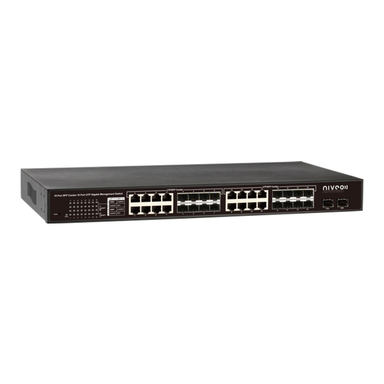
User Manual Niveo NGS18T16 16 10/100/1000BaseT(X) UTP/SFP combo ports and 2 Gigabit SFP Open Slots Management Switch... -
Page 2: Fcc Warning
FCC Warning This Equipment has been tested and found to comply with the limits for a Class-A digital device, pursuant to Part 15 of the FCC rules. These limits are designed to provide reasonable protection against harmful interference in a residential installation. This equipment generates, uses, and can radiate radio frequency energy. -
Page 3: Table Of Contents
Content Introduction ........................4 Product Overview ......................4 Web Management Features ..................4 Specifications ........................ 4 Mechanical ........................5 Performance ........................5 Package Contents ......................5 Hardware Description ...................... 6 Physical Dimensions/ Weight ..................6 Front Panel ........................6 LED Indicators ......................6 Rear Panel........................ - Page 4 Ping........................... 30 Maintenance ........................ 31 Warm Restart ......................31 Factory Default ....................... 32 Software upload ...................... 32 Configuration File Transfer ................... 32 Logout ........................33...
-
Page 5: Introduction
Introduction Product Overview This switch is a Management Switch equipped with 16 10/100/1000BaseT(X) UTP/SFP combo ports + 2 Gigabit SFP Open Slots. It is designed for easy installation and high performance in an environment where traffic is on the network and the number of users increased continuously. The compact rigid 19” rack-mount size is specifically designed for small to medium workgroups. -
Page 6: Mechanical
IEEE 802.3z 1000BaseSX/LX IEEE 802.3x Flow Control IEEE 802.1x Port-based Network Access Control IEEE 802.1Q VLAN Tagging IEEE 802.3ad Port Aggregation IEEE 802.1d Spanning tree protocol IEEE 802.1w Rapid Spanning tree protocol IEEE 802.1p Class of service, Priority Protocols Number of Port 16 10/100/1000BaseT(X) UTP/SFP combo ports + 2 Gigabit SFP Open Slots Mechanical ... -
Page 7: Hardware Description
Hardware Description This part primarily presents hardware of the web-smart switch, physical dimensions and functional overview would be described. Physical Dimensions/ Weight 44 × 440 × 220 mm (H × W × D) /3kg Front Panel The front Panel of the web-smart Switch consists of 16 10/100/1000BaseT(X) UTP/SFP combo ports + 2 Gigabit SFP Open Slots. -
Page 8: Rear Panel
Rear Panel The 3-pronged power plug is placed at the rear panel which is on the right side of the switch shown as below. Hardware Installation Set the switch on a large flat space with a power socket close by. The flat space should be clean, smooth, level and sturdy. -
Page 9: Software Description
Software Description This part instructs user how to set up and manage the switch through the web user interface. Please follow the description to understand the procedure. At the first, open the web browser, and go to 192.168.2.1 site then the user will see the login screen. -
Page 10: Configuration
Configuration System System Configuration This page shows system configuration information. User can configure lots of information as below: Figure 2-1 MAC Address: Displays the unique hardware address assigned by manufacturer (default). S/W Version: Displays the switch’s firmware version. ... -
Page 11: Ports
Management VLAN: ID of a configured VLAN (1-4094) through which you can manage the switch. By default, all ports on the switch are members of VLAN 1. However, if the management VLAN is changed, the management station must be attached to a port belonging to this VLAN. ... -
Page 12: Vlan
Figure 2-2 VLAN A Virtual LAN (VLAN) is a logical network grouping that limits the broadcast domain, which would allow you to isolate network traffic, so only the members of the same VLAN will receive traffic from the ones of the same VLAN. Basically, creating a VLAN from a switch is logically equivalent of reconnecting a group of network devices to another Layer 2 switch. -
Page 13: Aggregation
Figure 2-3 Aggregation Port trunk allows multiple links to be bundled together and act as a single physical link for increased throughput. It provides load balancing, and redundancy of links in a switched inter-network. Actually, the link does not have an inherent total bandwidth equal to the sum of its component physical links. -
Page 14: Lacp
LACP IEEE 802.3ad Link Aggregation Control Protocol (LACP) increases bandwidth by automatically aggregating several physical links together as a logical trunk and providing load balancing and fault tolerance for uplink connections. LACP Port Configuration Port: The port number. Enabled: Enables LACP on the associated port. ... - Page 15 recovery from failed links, enhancing overall network stability and reliability. RSTP System Configuration System Priority: This parameter configures the spanning tree priority globally for this switch. The device with the highest priority becomes the STP root device. However, if all devices have the same priority, the device with the lowest MAC address will then become the root device.
-
Page 16: 802.1X
Figure 2-6-2 802.1X 802.1X provides port-based authentication, which involves communications between a supplicant, authenticator, and authentication server. Port refers to a single point of attachment to the LAN infrastructure. The supplicant is often software on a client device, such as a laptop; the authenticator us a network device, such as an Ethernet switch or wireless access point;... -
Page 17: Igmp Snooping
802.1X Configuration Mode: Enables or disables 802.1X globally for all ports on the switch. The 802.1X protocol must be enabled globally for the switch before the port settings are active. (Default: Disabled) RADIUS IP: Address of authentication server. ... -
Page 18: Mirroring
switch adds the host’s port number to the multicast list for that group. Moreover, when the switch hears an IGMP Leave, it removes the host’s port from the table entry. Prevents flooding of IP multicast traffic, and limits bandwidth intensive video traffic to only the subscribers. -
Page 19: Quality Of Service (Qos)
Figure 2-9 Quality of Service (QoS) In QoS Mode, select QoS Disabled, 802.1p, or DSCP to configure the related parameters. QoS Configuration Strict: Services the egress queues in sequential order, transmitting all traffic in the higher priority queues before servicing lower priority queues. ... - Page 20 Figure 2-10-1 QoS Mode: QoS Disabled When the QoS Mode is set to QoS Disabled, the following table is displayed. QoS Mode: 802.1p Packets are prioritized using the 802.1p field in the VLAN tag. This field is three bits long, representing the values 0 - 7. When the QoS Mode is set to 802.1p, the 802.1p Configuration table appears, allowing you to map each of the eight 802.1p values to a local priority queue (low, normal, medium or high).
-
Page 21: Filter Configuration
all DSCP values to the high priority egress queue. User can use the Prioritize Traffic drop-down list to quickly set values into the DSCP Configuration table which is a common priority queue. Use Custom if you want to set each value individually. When the QoS Mode is set to DSCP, the DSCP Configuration table is displayed as shown below. - Page 22 Figure 2-11 Source IP Filter: Mode: There are three types of mode in this drop-down menu. Default is disabled. Disabled: Allow all IP network addresses to login to this switch and manage it. Static: Only the configured IP network address (IP with IP mask) is allowed to login to this switch and manage it.
-
Page 23: Rate Limit Configuration
IP Address: Setting up the IP Address, it can be one IP Address or a LAN. IP Mask: Setting up the IP Subnet Mask related with the IP Address. DHCP Server Allowed: Just tick the check box under the port x to allow the DHCP Server on this port and valid port is Port 1~18. -
Page 24: Storm Control
Figure 2-12 Storm Control Broadcast storms may occur when a device on your network is malfunctioning, or if application programs are not well designed or properly configured. If there is too much broadcast traffic on your network, performance can be severely degraded or everything can come to complete halt. -
Page 25: Monitorning
ICMP Rate, Learn Frames Rate, Broadcast Rate, Multicast Rate and Flooded unicast Rate. The setting range is 1k~32768k per second. Default of four Rates is No Limit. Figure 2-13 After completing the function’s setting, press <Apply> button to have this function taken effect. -
Page 26: Detailed Statistics
analysis the following figures shows clearly the statistics overview. Figure 3-1 Detailed Statistics Display the detailed counting number of each port’s traffic. In the list, the window can show all counter information each port at one time. Figure 3-2 LACP Status LACP Aggregation Overview... - Page 27 Figure 3-3-1 Port: The port number. Port Active: Shows if the port is a member of an active LACP group. Partner Port Number: A list of the ports attached at the remote end of this LAG link member. ...
-
Page 28: Rstp Status
RSTP Status RSTP VLAN Bridge Overview Figure 3-4-1 Bridge Id: Show this switch’s current bridge priority setting and bridge ID which stands for the MAC address of this switch. Hello Time: Interval (in seconds) at which the root device transmits a configuration message. - Page 29 Figure 3-4-2 Port/Group: The number of a port or the ID of a static trunk. Path Cost: The cost for a packet to travel from this port to the root in the current Spanning Tree configuration. The slower the media, the higher the cost.
-
Page 30: Igmp Status
IGMP Status IGMP Status IGMP Status shows the IGMP Snooping statistics for the whole switch. VLAN ID: VLAN ID number. Querier: Show whether Querying is enabled. Queries transmitted: Show the number of transmitted Query packets. Queries received: Show the number of received Query packets. ... -
Page 31: Ping
Figure 3-6 Ping This command sends ICMP echo request packets to another node on the network. Ping Parameters Target IP Address: IP address of the host Count: Number of packets to send. Four type of number can choose (1, 5, 10 and 20). -
Page 32: Maintenance
Figure 3-7 Maintenance The switch offers many approaches to reboot your switch, such as: power up, hardware reset and software reset. You can press RESET button in the front panel of your switch to reset the device and to retrieve default settings. After upgrading software, you have to reboot the device to have new configuration take effect. -
Page 33: Factory Default
Factory Default Factory Default provides the function to retrieve default settings and replace current configuration. Except the IP address setting, all settings will be restored to the factory default values when “Factory Default” function is performed. If you want to restore all configurations including the IP address setting to the factory default, please press the “RESET”... -
Page 34: Logout
Figure4-4 Logout The administrator has the authority to write and access for all parameters governing the onboard agent. User should therefore assign a new administrator password as soon as possible, and store it in a safe place. Figure 4-5...
Need help?
Do you have a question about the NGS18T16 and is the answer not in the manual?
Questions and answers