Table of Contents
Advertisement
Quick Links
Advertisement
Table of Contents
Troubleshooting

Related Manuals for Exodraft BD

Summary of Contents for Exodraft BD
- Page 1 Heat Recovery | Read and save these instructions! Your energy. Optimized.
-
Page 3: Table Of Contents
Your energy. Optimized. Heat Recovery | Bypass Damper Content Product information Scope of supply Accessories and spare parts Warranty Technical specifications Mechanical installation Placement and orientation Mounting Mounting points Connection Installation without water connection Electrical installation Placement of Safety Thermostat Operating conditions Primary-/Flue Gas Side Secondary-/Liquid Side... - Page 4 How to use this manual This manual has been prepared based on the specific product and contains relevant technical information and installations guides. Accessories and spare parts are not covered by this manual. Please refer to the individual manuals of these components. This installation manual does not contain any system design documentation.
- Page 5 Symbols The following symbols may be used in the manual to draw attention to danger or risk of personal injury or damage to the product. General prohibition Failure to observe instructions marked with the prohibited symbol may result in extreme danger or serious personal injury. General attention Marks a dangerous situation that, in the worst-case scenario, can cause serious personal injury or significant damage to the product.
- Page 6 • Please always read the manual and only use the product in accordance with the manufacturer’s instructions. If in doubt, contact one of the Exodraft specialized dealers. • All installations must be carried out by properly qualifi ed personnel in accordance with national legislation and regulations.
-
Page 7: Product Information
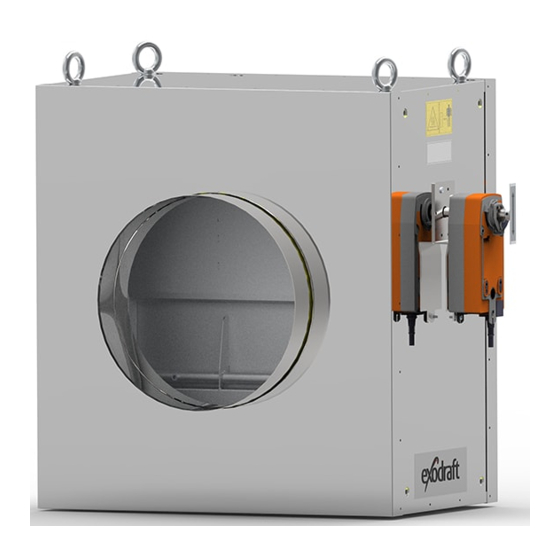
A Bypass Damper is used primarily for larger boiler systems, industrial processing plants, or commercial systems. An integrated electric motor opens and closes the damper. Power supply and start/stop signal come from an external Exodraft panel, and is not a part of the Bypass Damper. -
Page 8: Accessories And Spare Parts
Damper motor NFA 10 Nm 3201079 Damper motor GK24 40 Nm *This manual does not describe the specific use of spare parts. We refer to the separate manuals for such components. For more details contact your Exodraft dealer. 8 | UK... -
Page 9: Warranty
3112027_BD_UK Warranty All Exodraft products are covered by a 2-year guarantee as per European consumer rights legislation. For some countries an extended period of guarantee may apply depending on either national legislation or other clearly stipulated conditions. Customer complaints must be handled by a specialised dealer or wholesaler (preferably where the Exodraft product has been bought originally). -
Page 10: Technical Specifications
Your energy. Optimized. Technical specifications Basic types Exodraft item Type Inlet Ø Outlet Ø Description number (Bypass Damper) exterior [mm] interior [mm] Bypass Damper with motor Standard pipe connection 250.50 251.20 8003300 BD250 dimensions Max 600 Bypass Damper with motor... - Page 11 3112027_BD_UK Standard components Outlet Housing M12 thread for mounting, three at each corner Damper motor (can be installed at both sides of the axle for reverse function) Nameplate Danger/Caution sign Inlet Outlet Damper (inside) UK | 11...
- Page 12 Your energy. Optimized. Technical data Dimensions [mm] Model BD250 253.20 253.20 250.50 BD350 353.20 353.20 350.50 610.40 BD400 403.20 403.20 400.50 610.40 BD500 503.20 503.20 500.50 610.40 BD700 703.20 703.20 700.50 610.40 *Specifies inside sleeve dimensions **Specifies outside adapter dimensions 12 | UK...
-
Page 13: Mechanical Installation
CAUTION! If the Exodraft Bypass Damper is not installed, maintained, and/or operated in compliance with the manufac- turer’s instructions, conditions may arise which could lead to personal injury or material damage. -
Page 14: Mounting
Mounting points are only intended to support the weight of the product itself. Bypass Damper is not built to support the weight of any chimney. DANGER! Max. load on mounting corner 100kg Exodraft item Type (Bypass Weight incl. heat Number of heat... - Page 15 3112027_BD_UK 8002301 BD250-2 17,5 Model A [mm] B [mm] BD250 66.50 BD500 66.50 BD750 66.50 BD1000 66.50 BD2000 66.50 UK | 15...
-
Page 16: Mounting Points
Your energy. Optimized. 8002500 BD500 17.50 8002501 BD500-2 17.50 8002600 BD750 8002601 BD750-2 3 x M12 tread DETAIL A 8002700 BD1000 17.50 8002701 BD1000-2 17.50 8002800 BD2000 17.50 8002801 BD2000-2 17.50 Mounting points Bypass Damper must be fitted in at least four different corners of the product. In addition, for safety reasons, it must be ensured that the weight of the product is evenly distributed over all four assembly points. -
Page 17: Connection
3112027_BD_UK Connection • Connection on heat exchangers is 1 1/4” outside thread • Connection to drain is 1” inside thread • Connection to measuring points is ½” inside thread CAUTION! Bypass Damper comes with heat exchangers temporarily mounted for shipping. When installing, the included gaskets, nuts, and washers must be fitted. - Page 18 Your energy. Optimized. As a rule, the washer for the heat exchanger can be used only once. 18 | UK...
-
Page 19: Installation Without Water Connection
3112027_BD_UK 8 12 9 11 7 When selecting gasket material, keep in mind that the temperature for drains and measuring points can be the same as the temperature of the flue gas. We recommend installing a water trap on the drain connection. The water trap should be placed a good distance from the Bypass Damper to avoid the water evaporating. - Page 20 Your energy. Optimized. Water connection for BD250 Water connection for BD250-2 Water connection for BD500 Water connection for BD500-2 Project: Title: Error: No reference Draw. No.: Material: Format: A3 Date: 31-05-2017 Rev. No.: Ref.: Weight: 0,000 kg Error: No reference Rev.: Sheet: 1 of 2...
- Page 21 3112027_BD_UK Water connection for BD750/1000 Water connection for BD750/1000-2 Water connection for BD2000 Water connection for BD2000-2 Project: Title: Error: No reference Draw. No.: Material: Format: A3 Date: 31-05-2017 Rev. No.: Ref.: Weight: 0,000 kg Error: No reference Rev.: Sheet: 1 of 2 Approved: Error: No refer ence...
-
Page 22: Electrical Installation Placement Of Safety Thermostat
Your energy. Optimized. 10 11 Electrical installation Placement of Safety Thermostat CAUTION! If using safety thermostat ST110, it must be placed away from the heat source, so the ambient temperature of the sensor is as low as possible. If this is not complied with, the boiler may be disabled inadvertently. 22 | UK... -
Page 23: Operating Conditions
3112027_BD_UK Operating conditions Primary-/Flue Gas Side • Max. flue gas temperature: 600°C • Max. working pressure: 5000 Pa • Min. working pressure: -5000 Pa Heat Kedel source Min. X meter Project: Title: Draw. No.: Error: No reference Material: Format: A3 Date: 31-05-2017 0,000 kg... -
Page 24: Secondary-/Liquid Side
Max. media temperature is dependent on the surface temperature and the used media Startup and configuration The purpose of this Exodraft Bypass Damper heat recovery unit is to recover surplus energy from flue gas- ses and process air. The unit is environmentally friendly, economical, and compact. -
Page 25: System Startup
Connect the water and bleed the system If condensation is a possibility, connect the drain to an appropriate outlet Activate the circulation pump (not supplied by Exodraft) and check that it’s running Check that system pressure is consistent with system pressure tables in section 8... - Page 26 Reattach hose/pipe connections to exchanger Follow directions in point 5.2 as far as restarting the system CAUTION! Use gloves and protective glasses when cleaning the exchanger. Note: The exchangers are heavy – see weight table below. Exodraft Exchanger Number of Weight per...
-
Page 27: Troubleshooting
3112027_BD_UK Troubleshooting Observation Problem Solution There is air in the water system The system needs to be bled The circulation pump is not operating Check the operation of the circulation correctly pump The water flow is too fast Check the operation of the circulation pump and mixing loop The supply water temperature is low and the temperature difference... -
Page 28: System Pressure
Your energy. Optimized. System pressure System pressure is tested according to these standards: 2014/68/EU Fluid Group: 1 & 2 201, 2006/42/EF and 2014/35/EU System pressure BD250 - 1. step Minimum system pressure [bar Exhaust temperature [°C] Exhaust temperature [°C] Δt Δt Water Water... - Page 29 3112027_BD_UK System pressure BD500 - 1. step Minimum system pressure [bar Exhaust temperature [°C] Exhaust temperature [°C] Δt Δt Water Water sample sample 1.50 1.50 1.50 1.50 1.50 1.50 1.50 1.50 1.50 1.50 temperature temperature 1.50 1.50 1.50 1.50 1.50 1.50 1.50 1.50...
- Page 30 Your energy. Optimized. System pressure BD750 - 1. step Minimum system pressure [bar Exhaust temperature [°C] Exhaust temperature [°C] Δt Δt Water Water sample sample 1.50 1.50 1.50 1.50 1.50 1.50 1.50 1.50 1.50 1.50 temperature temperature 1.50 1.50 1.50 1.50 1.50 1.50...
- Page 31 3112027_BD_UK System pressure BD1000 - 1. step Minimum system pressure [bar Exhaust temperature [°C] Exhaust temperature [°C] Δt Δt Water Water sample sample 1.50 1.50 1.50 1.50 1.50 1.50 1.50 1.50 1.50 1.50 temperature temperature 1.50 1.50 1.50 1.50 1.50 1.50 1.50 1.50...
- Page 32 Your energy. Optimized. System pressure BD2000 - 1. step Minimum system pressure [bar Exhaust temperature [°C] Exhaust temperature [°C] Δt Δt Water Water sample sample 1.50 1.50 1.50 1.50 1.50 1.50 1.50 1.50 1.50 1.50 temperature temperature 1.50 1.50 1.50 1.50 1.50 1.50...
- Page 33 3112027_BD_UK UK | 33...
-
Page 34: Uk Conformity Assessed
UK Conformity Assessed UK Conformity Assessed Exodraft a/s Industrivej 10 DK-5550 Langeskov Hereby declares that the following products: BD250, BD250-2, BD500, BD500-2, BD750, BD750-2, BD1000, BD1000-2, BD2000, BD2000-2 Were manufactured in conformity with the provisions of the following regulations: The Supply of Machinery (Safety) Regulations 2008... -
Page 35: Declaration Of Conformity
EU-Vaatimustenmukaisuusvakuutus Déclaration de conformité de l’Union Européenne ESS-Samræmisstaðfesting EU-Samsvarserklæring Dichiarazione di Conformità Unione Europea EU Deklaracja zgodności Exodraft a/s Industrivej 10 DK-5550 Langeskov Erklærer på eget ansvar, at følgende produkter: Veklaart dat onderstaande producten: Hereby declares that the following products: Deklarerar på... - Page 36 DK: Exodraft a/s Industrivej 10 DK-5550 Langeskov Tel: +45 7010 2234 Fax: +45 7010 2235 info@exodraft.dk www.exodraft.dk SE: Exodraft a/s Kalendevägen 2 SE-302 39 Halmstad Tel: +46 (0)8-5000 1520 info@exodraft.se www.exodraft.se NO: Exodraft a/s Storgaten 88 NO-3060 Svelvik Tel: +47 3329 7062 info@exodraft.no...
Need help?
Do you have a question about the BD and is the answer not in the manual?
Questions and answers