Advertisement
Quick Links
While this cab kit was designed to fit on the vehicle listed above, manufacturing tolerances and vehicle
assembly may affect cab fitment. It is the responsibility of the cab installer to check all vehicle pedals and
levers for full functionality and, as required, adjust the cab fitment to prevent any interference of the cab
components with the travel of pedals or levers.
Available Options:
1. Side View Mirrors (P/N: 9PM5)
2. Switch Panel (P/N: 1FISX33CK) (required for the following 2 items)
3. Front LED Work Lights (P/N: 1ZTRLK)
4. Front Wiper/Washer Kit (P/N: 1ZTRWK)
Approximate Installation Time *
Experienced Dealer Technician – 4 Hours
Average Dealer Technician – 6 Hours
Do-It-Yourself – 6-8 Hours
(*=Not including accessories)
Register your new product quickly online at
Curtiscab.com/product-registration/
Curtis encourages all customers to register their
Curtis products. However, failure to do so will not
diminish right to warranty. Curtis Industries does not
sell or share your information with anyone else.
The contents of this envelope are the property of the owner. Leave with the owner when installation is complete.
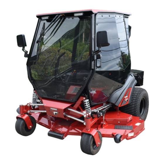
Ferris ISX 3300
(p/n: 1FISX33PR)
Cab with A/C
(fits both 60" and 72" mowers)
(does not fit with bagger systems)
Premium Cab Shown with Options
Approximate Product Specifications
Floorboard to Roof Height: 57 inches
Weight: 252 lbs.
Cab Width: 50 inches
Download a digital copy of your installation
instructions online at Curtiscab.com/literature/
Curtis strives to continuously improve our products,
technical documentation, etc. Therefore, the
installation manual for this product may have been
updated after your product was packaged. The
latest revision of the installation manual can always
be found at the website above.
Rev. A, 12/21/2022
p/n: IM-1FISX33PR
1 of 23
Advertisement

Subscribe to Our Youtube Channel
Related Manuals for Curtis Ferris ISX 3300


Summary of Contents for Curtis Ferris ISX 3300
- Page 1 Therefore, the Curtis encourages all customers to register their installation manual for this product may have been Curtis products. However, failure to do so will not updated after your product was packaged. The diminish right to warranty. Curtis Industries does not latest revision of the installation manual can always sell or share your information with anyone else.
-
Page 2: Table Of Contents
2 of 23 TABLE OF CONTENTS WARNINGS, TIPS, & REQUIRED TOOLS ............3 VEHICLE PREP ................... 4-5 CAB INSTALLATION .................. 6-14 CAB FEATURES & OPERATION ..............15 CARE AND MAINTENANCE ................. 16 TROUBLESHOOTING .................. 16 SERVICE PARTS ..................17-22 BOLT TORQUE SPECIFICATIONS .............. 23... -
Page 3: Warnings, Tips, & Required Tools
3 of 23 WARNINGS, TIPS, & REQUIRED TOOLS Curtis cabs feature an assembly of parts designed for your vehicle which require adjustment and alignment of components to accommodate vehicle variations and provide proper weather protection. For accurate installation, proper operation, and years of satisfaction, please read and understand the installation and owner’s manual fully prior to installing the cab. -
Page 4: Vehicle Prep
4 of 23 CAB INSTALLATION Step 1: (Vehicle Engine Prep) Remove Remove 1.1 Park vehicle in a location accessible by an overhead hoist. 1.2 Disconnect the negative battery terminal. Tools Required 7/16” wrench or socket 1.3 See fig. 1.3. Remove the upper wire screen and lower mesh screen from the top of the vehicle’s engine. - Page 5 5 of 23 CAB INSTALLATION Step 1: (Vehicle Engine Prep, continued) 1.7 See fig. 1.7. Loosen the set screw on the pulley from the hardware box until it does not protrude into the slot. Place the machine key from the hardware kit into the slot in the stub shaft and slide the pulley over the shaft aligned to the key, then tighten the set screw.
- Page 6 6 of 23 CAB INSTALLATION Step 3: (Install Cab Mounts) Ref.: threaded inserts here (2x) CAUTION: Work on the following steps one side at a time so that the opposite side will remain fastened. 3.1 See fig. 3.1. Remove the 1/2” bolt and nut from the bottom of the right side of the vehicle ROPS.
- Page 7 7 of 23 CAB INSTALLATION Step 4: (Cab Installation) 4.1 See fig. 4.1. Set the deck height for the mower to 3-1/2”. This will place the height adjustment lever to a near vertical position for minimal interference with the cab as it’s lowered. 4.2 Remove the doors from the cab and set aside carefully to prevent scratching the panels.
- Page 8 8 of 23 CAB INSTALLATION Step 5: (A/C Compressor Installation) 1/2” ROPS bolt 5.1 See fig. 5.1. Place the front flange of the A/C compressor bracket over the 1/2” ROPS bolt on the left side ROPS and loosely place a nut over the bolt.
- Page 9 9 of 23 CAB INSTALLATION Step 6: (A/C and Cab Wiring, continued) 6.6 Route the A/C harness towards the rear of the mower, between the engine and compressor mount, then out through the bottom of the “F” on the side of the mower rear body. 6.7 See Fig.
- Page 10 10 of 23 CAB INSTALLATION Step 7: (A/C V-belt) M6 bolts 7.1 See fig. 7.1. Install the Flywheel Shroud Mount to the engine housing using 3 of the 4 M6 screws removed in step 1.3, and to the compressor mount with three 1/4”...
- Page 11 11 of 23 CAB INSTALLATION Step 8: (A/C Cover Panels) 8.1 See fig. 8.1. Install the Compressor Debris Cover onto the A/C compressor mount as shown. Tools Required 3/8” hex wrench or socket Hardware Used 1/4-20 bolts 1/4-20 x 5/8” Flanged Hex Bolt 1/4-20 bolts 8.2 Per fig.
- Page 12 12 of 23 CAB INSTALLATION Step 9: (Cab Filler Panels) 9.1 See fig. 9.1. Place the longer strip of self-adhesive arch foam (7” long) onto edge of the bend on the left side of the deck height adjustment pin box. Hardware Used Arch P.S.A.
- Page 13 13 of 23 CAB INSTALLATION Step 9: (Cab Filler Panels, continued) Right side bracket 9.7 Rotate the seat forward. Per fig. 9.7, remove the rear bolt from the right control arm mechanism. Place the right inner filler bracket on the outside of the vehicle’s frame flange, then secure with a 5/16”...
- Page 14 14 of 23 CAB INSTALLATION Step 9: (Cab Filler Panels, continued) 9.11 See fig. 9.11. Attach the headrest mount assembly (from step 2.4) to the rear frame with thumb screws and fender washers. Adjust the height of the headrest as desired, then tighten the thumb screws finger tight.
-
Page 15: Cab Features & Operation
15 of 23 CAB FEATURES & OPERATION AIR CONDITIONING OPERATION Turn the 4-position ventilation switch to activate the blower. This can be used as just a blower with the A/C compressor turned off. Rotate the A/C switch to the desired temperature setting to turn the compressor on/off. -
Page 16: Care And Maintenance
16 of 23 CARE AND MAINTENANCE •DO NOT use glass cleaner to clean windows. It will damage the material. Mild dish soap and water should be used to clean all window panels. Use a soft bristled brush or sponge to clean panels. •Avoid wiping the windows while they are dry. -
Page 17: Service Parts
17 of 23 SERVICE PARTS ROOF ASSEMBLY WINDSHIELD ASSEMBLY WINDSHIELD SUPPORT ASSEMBLY P/N: 8SV-102-00040 P/N: 8SV-103-00030 P/N: 8SV-101-00066 REAR PANEL ASSEMBLY DOOR ASSEMBLY, RIGHT DOOR ASSEMBLY, LEFT P/N: 8SV-106-00045 P/N: 8SV-107-00058-L P/N: 8SV-107-00058-R SIDEFRAME ASSEMBLY, LEFT SIDEFRAME ASSEMBLY, RIGHT FRONT FLOORBOARD ASSEMBLY P/N: 8SV-109-00027-R P/N: 8SV-105-00035 P/N: 8SV-109-00027-L... - Page 18 18 of 23 SERVICE PARTS UPPER REAR PANEL A/C UNIT, REAR MOUNTED A/C COVER ASSEMBLY P/N: 8SV-111-00043 P/N: 8SV-303-00013-BP P/N: 8SV-302-00008-BP ROPS MOUNT, LEFT ROPS CLAMP, LEFT ROPS MOUNT, RIGHT P/N: 8SV-110-00110-L P/N: 8SV-111-00110-R P/N: 8SV-110-00111-L ROPS CLAMP, RIGHT V-BELT A/C AIR DIVERTER FLAP P/N: 8SV-110-00111-R P/N: 8SV-113-00258-BP...
- Page 19 19 of 23 SERVICE PARTS FRONT MOUNT BRACKET, LEFT FRONT MOUNT BRACKET, RIGHT COMPRESSOR BRACKET P/N: 8SV-SM-02296-R P/N: 8SV-WA-00567 P/N: 8SV-SM-02296-L FLYWHEEL SHROUD FLYWHEEL SHROUD MOUNT COMPRESSOR DEBRIS COVER P/N: 8SV-113-00300 P/N: 8SV-113-00342 P/N: 8SV-113-00312 REGULATOR MOUNT BRACKET ACCESS COVER, RECHARGE PORT CRANKSHAFT PULLEY P/N: 8SV-SM-02449 P/N: 8SV-MP-00083...
- Page 20 20 of 23 SERVICE PARTS REAR LEG WINDOW, LEFT W/ HOSE, #10 EVAP TO COMP HOSE, #6, COND TO DRYER P/N: 8SV-305-00025 HARDWARE P/N: 8SV-305-00026 P/N: 8SV-P-00161-L DOOR SKIN, LEFT, W/ HARDWARE REAR LEG WINDOW, RIGHT W/ DOOR SKIN, RIGHT, W/ HARDWARE P/N: 8SV-P-00163-L P/N: 8SV-P-00163-R HARDWARE...
- Page 21 21 of 23 SERVICE PARTS DECK CONTROL COVER INNER FILLER BRACKET, LEFT INNER FILLER BRACKET, RIGHT P/N: 8SV-111-00042 P/N: 8SV-110-00119-L P/N: 8SV-110-00119-R SEAT LEVER SEAL PANEL UNDER SEAT FILLER ASSEMBLY, LEFT UNDER SEAT FILLER ASSEMBLY, RIGHT P/N: 8SV-111-00049 P/N: 8SV-111-00047-L P/N: 8SV-111-00047-R LEFT FLOORBOARD FILL PANEL DRIVE HANDLE FILLER, LEFT...
- Page 22 22 of 23 ADDITIONAL SERVICE PARTS PART NUMBER DESCRIPTION 9SV-HWK-00187 HARDWARE KIT, PREP AND CAB INSTALL 9SV-HWK-00188 HARDWARE KIT, COVER PANELS 9SV-OHRL-G OUTSIDE DOOR HANDLE (SET OF 2) 9SV-GH INTERIOR GRAB HANDLE (SET OF 2) 9SV-HSLP HINGE PINS AND SLEEVES (2L + 2R) 9SV-DP10 DOME PLUG, .375”...
-
Page 23: Bolt Torque Specifications
23 of 23 BOLT TORQUE BOLT TORQUE SPECIFICATIONS GENERAL TORQUE SPECIFICATION TABLE Use the following torques when special torques are not given. These values apply to fasteners as received from suppliers, dry, or when lubricated with normal engine oil. They do not apply if special graphited or moly disulphide greases or other extreme pressure lubricants are used.
Need help?
Do you have a question about the Ferris ISX 3300 and is the answer not in the manual?
Questions and answers