Table of Contents
Advertisement
Quick Links
HIGH-FREQUENCY
INDUCTION HEATER
This manual shall be made available to all users of this high-frequency induction
heater. To ensure the best results and maximum durability of this U.S. SOLID LLC
(hereafter U.S. SOLID or The Company) product, read and follow all instructions
carefully. Failure to do so may lead to serious bodily injury and catastrophic
damage to the heater, supplies, or surrounding area. All safety suggestions must
be followed closely and precautions must be taken to guarantee this heater is
only used by qualified personnel who have understood this guide.
Version 2.0 ©2022 U.S. SOLID LLC. All rights reserved.
For questions or concerns, email: service@ussolid.com
USS-HFIH00001-110V
USS-HFIH00001-220V
Advertisement
Table of Contents

Subscribe to Our Youtube Channel
Related Manuals for U.S. Solid USS-HFIH00001-110V


Summary of Contents for U.S. Solid USS-HFIH00001-110V
- Page 1 USS-HFIH00001-220V This manual shall be made available to all users of this high-frequency induction heater. To ensure the best results and maximum durability of this U.S. SOLID LLC (hereafter U.S. SOLID or The Company) product, read and follow all instructions carefully.
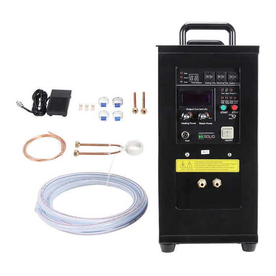
- Page 2 Parts Part Quantity ① Foot pedal ② Fuse ③ Clamps (stainless steel) 2x (each ∼0.5 ft long) ④ Tubing (copper) to connect your own coil ⑤ Tubing (copper) to create your own coil 1x (∼5 ft long) ⑥ Coil (copper) 1x (∼3.3 ft long) ⑦...
-
Page 3: Table Of Contents
Contents I. Operating Principles ................1 II. Getting Started ..................2 III. Safety Instructions ................3 IV. Setting Up ................... 4 V. Back of the Heater ................5 VI. Front Panel in Auto Mode ..............6 VII. Operating the Heater in Auto Mode ..........10 VIII. -
Page 4: Operating Principles
I. Operating Principles Induction heating is a contact-free heating process which uses high-frequency electricity to generate heat. When an alternating current (AC) flows through the coil while a workpiece is positioned inside, an electromagnetic field is generated. Once the current alternates (i.e., changes) direction, the direction of the electromagnetic field also changes. -
Page 5: Getting Started
Changes in technology happen often and rapidly, which is why our team at U.S. SOLID reserves the right to modify the specifications and procedures for this high-frequency induction heater immediately and without notice. The Company will not assume responsibility for equipment damage or malfunction due to improper operation, incorrect repairs, or use of unauthorized parts. -
Page 6: Safety Instructions
III. Safety Instructions This machine should only be operated by adults who have read and fully understood this manual. Always make sure the machine is grounded. Keep the area around the machine clean and free of debris. ... -
Page 7: Setting Up
IV. Setting Up When first receiving the induction heating machine, be careful when removing the machine from its box. This product is a heavy piece of equipment. The machine comes with one assembled coil, and one piece of copper tubing to create your own coil. -
Page 8: Back Of The Heater
V. Back of the Heater Notice where the water inlet and water outlet in this photo of your heater are located. Also, note the ground wire screw, which is towards the bottom of your machine. In this image, the housing is flipped up to show where to connect the two current-carrying wires. -
Page 9: Front Panel In Auto Mode
VI. Front Panel in Auto Mode ① Heat Indicator: When lit, the machine is heating the workpiece. ② Retaining Indicator: When lit, heat is retained using the current set by the Retain Power Adjustment Knob. ③ Cooling Indicator: When lit, current is no longer running through the coil, allowing for the workpiece to cool down. - Page 10 VI. Front Panel in Auto Mode ⑤ Retaining Power Adjustment Knob: Controls the current when in heat retention mode. This is only applicable when the machine is in automatic mode. ⑥ Pedal Connector: If the foot pedal is connected to the machine, the machine can be controlled using the pedal instead of the Start/Stop Buttons on the machine.
- Page 11 VI. Front Panel in Auto Mode ⑩ Warning Lights (Over Volt, Over Temp, Over Current, Water Lack, and Phase Fail): When one of these light up, the machine will cease operating. Different lights indicate different issues: Either too much voltage or current is running, the machine is overheating, the water pressure to the machine is not high enough, or the phase power is failing.
- Page 12 VI. Front Panel in Auto Mode ⑪ Time (in seconds) given between zero and 99 seconds. Can be increased using the button below the numbers and decreased using the button above the numbers. Note: 99 and 00 both represent 99 seconds. ⑫...
-
Page 13: Operating The Heater In Auto Mode
VII. Operating the Heater in Auto Mode When the machine is in automatic mode, heating of the workpiece will be controlled by setting the Heating Time, Retaining Time, and Cooling Time. These numbers can be between zero and 99 seconds. Once your desired times are set, simply press the Start Button and insert the workpiece. -
Page 14: Front Panel In Manual Mode
VIII. Front Panel in Manual Mode ① Heat Indicator: When on, it indicates that heating is taking place. ② Retaining Indicator: When lit, heat is retained using the current set by the Retain Power Adjustment Knob. ③ Pedal Connection: If the foot pedal is connected to the machine, the machine can only be controlled using the pedal instead of the Start/Stop Buttons on the machine. - Page 15 VIII. Front Panel in Manual Mode ⑦ Warning Lights (Over Volt, Over Temp, Over Current, Water Lack, and Phase Fail): When one of these lights turns on, the machine will cease operating. Different lights indicate different issues. Either too much voltage or current is running, the machine is overheating, the water pressure to the machine is not high enough, or the phase power is failing.
-
Page 16: Operating The Heater In Manual Mode
IX. Operating the Heater in Manual Mode Adjust the Heat Power Adjustment Knob to the desired level, then press the pedal to energize the coil. Insert your workpiece into the coil to begin heating. The further the Heat Power Adjustment Knob is turned clockwise, the hotter your workpiece will get. Step 1: Flip the On/Off Switch to turn on the heater. -
Page 17: Potential Applications
XI. Potential Applications Application Type Notes Brazing Hybrid welding of different materials. Clean the surfaces to be used. Dimension of the workpiece should be less than 1.2 x 1.2 x 1.2 ". Diathermy The diameter of the workpiece should be less than 5 mm (3/16"). -
Page 18: Troubleshooting
XII. Troubleshooting Problem: Over Temperature Light comes on. Causes: • Machine overheated. • Water is too hot. Solutions: • Allow the machine time to cool off, then restart. • Ensure the water temperature is less than 40°C (104°F) before it enters the machine. - Page 19 XII. Troubleshooting Problem: The machine will not power on. Causes: • The circuit breaker is tripped. • The fuse is blown. • The connections between the power supply and the machine are loose. • The outlet does not have power. Solutions: •...
-
Page 20: Specifications
XIII. Specifications Model USS-HFIH00001-110V USS-HFIH00001-220V Max. Inductive Power 15 KW Max. Input Power 7 KW Input Voltage 110 V, Single Phase 220 V, Single Phase Fluctuating Frequency 30-80 KHz Output Current 200-600 A Max. Heating Temperature 1200°C (2192°F) Time Settings...
Need help?
Do you have a question about the USS-HFIH00001-110V and is the answer not in the manual?
Questions and answers