Table of Contents
Advertisement
Quick Links
MONITOR-COMMS INTERFACE
MC
524
MC524 Monitor Interface Manual
Version 1.0
Part# 840-07521-01
Publish date: November 1999
Euphonix Inc. 220 Portage Avenue Palo Alto , CA 94306
Tel: (650)855-0400 Fax: (650) 855-0410 Web Page:
www.euphonix.com
In the interest of continued product development, Euphonix reserves the right to make improvements in this manual and the
product it describes at any time, without notice or obligation.
System 5, S-5, PatchNet, eMix, EuCon, R-1, Studio Hub, , Digital Studio Controller, DSC, CleaR, GainBall, SnapShot,
SnapShot Automation, SnapShot Recall and Total Automation are trademarks of Euphonix Inc.
Advertisement
Table of Contents

Related Manuals for Euphonix MC524


Summary of Contents for Euphonix MC524
- Page 1 Tel: (650)855-0400 Fax: (650) 855-0410 Web Page: www.euphonix.com In the interest of continued product development, Euphonix reserves the right to make improvements in this manual and the product it describes at any time, without notice or obligation. System 5, S-5, PatchNet, eMix, EuCon, R-1, Studio Hub, , Digital Studio Controller, DSC, CleaR, GainBall, SnapShot,...
- Page 2 This page intentionally left blank MC524 Manual Version 1.0 Page 2 ©1999 Euphonix, Inc.
-
Page 3: Table Of Contents
TABLE OF CONTENTS MC524 MONITOR INTERFACE ..............4 Box Inventory...........................4 Safety and Precautions ......................4 System Setup..........................5 Power On Sequence ........................5 CE..............................5 Component Overview ......................6 Functional Description.......................6 Features.............................6 Applications..........................6 Physical Specifications ......................7 Dimensions..........................7 Front Panel ..........................7 Rear Panel Connectors......................8 Technical Specifications.......................9 Performance Specifications.......................9... -
Page 4: Mc524 Monitor Interface
3) Water and Moisture – Do not use the MC524 near water. 4) Heat – Locate the MC524 away from heat sources. 5) Power Sources – Connect the MC524 only to a power supply of the type described in these operation instructions or as marked on the MC524. -
Page 5: System Setup
THERE ARE NO USER SERVICEABLE PARTS IN THE MC524 System Setup The MC524 receives control information from the System 5 Interface Pilot via a 15 pin Dsub cable. All necessary connections to the MC524 are described in the cable specifications and hookup diagrams in this document. -
Page 6: Component Overview
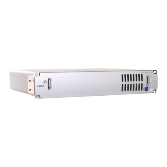
The MC524 Monitor Interface centralizes Control Room monitor and communication signals in one box and places them under remote control of the system operator. A digitally controlled analog signal router and level control device with a built in Talk Back microphone circuit, the MC524 is packaged in a 2RU enclosure. -
Page 7: Physical Specifications
Approximately 6 inches of depth should be left behind the MC524 for cable connections. Front Panel MONITOR-COMMS INTERFACE Power Switch On/Off button powers the unit up. Since the MC524 is digitally controlled via software, there are no other user controls on the front panel. MC524 Manual Version 1.0 Page 7 ©1999 Euphonix, Inc. -
Page 8: Rear Panel Connectors
(90 pin ELCO) Monitor A, B, C, D Speaker outputs. This connector is mapped to output 8 Control Room channels, 8 Monitor A channels, and 2 each channels for Monitor B, C, D, and Solo. The output cable fans out to 2-38 pin ELCO/Edak connectors for the Euphonix Patchbay. Out 2 (90 pin ELCO) Control Room Speakers, Talk Back and Listen Back Preamp, and Solo Busses outputs. -
Page 9: Technical Specifications
Electronically balanced, transformerless, differential input Gain: Variable from unity (0dB) to –72dB Optimum input levels: Designed to be fed from Euphonix MA703 DAC, set to 0dBFS = +27dBU Maximum input level before clipping: +28dBU (sine wave) ±16VDC, ±25VAC (common mode), ±50VAC (differential) Maximum input voltages: 10KΩ... -
Page 10: Phantom Power: 48V Jumper Settings
J3: Listen 1 (L1) Lower board: J1: Listen 2 (L2) J2: Listen 3 (L3) J3: Listen 4 (L4) Environmental Requirements 5 to 35 degrees Centigrade. Power Requirements 90- 240 VAC, 50/60Hz. Power Consumption MC524 Manual Version 1.0 Page 10 ©1999 Euphonix, Inc. -
Page 11: User Reference
User Reference MC524 Manual Version 1.0 Page 11 ©1999 Euphonix, Inc. -
Page 12: Cable Specification - Standard Configuration
TCC Control from 253I Interface Pilot 030-06983-01 030-06985-01 TB/LB Mic, (1EM38<>12xXLRF) 030-06919-01 CR/Mon/Solo Bus (1XEM90<>24xXLRF) 030-07225-01 TB &LB Mic Pre Out (1xDB25<>8xXLRM) 032-07038-00 Elco 90 Pin Connector w/hood 100-07470-00 Elco Crimp Pins 100-02100-00 (180) MC524 Manual Version 1.0 Page 12 ©1999 Euphonix, Inc. -
Page 13: Hookup Diagram - Standard Configuration
(TB1 returns to 8 - CR Main out 2 - Mon D core for slate) 6 - CR Alt 1 out 2 - CR Alt 2 out 7, 8 Connectors and pins provided MC524 Manual Version 1.0 Page 13 ©1999 Euphonix, Inc. -
Page 14: In 1 Pinout, Elco 38
In 1 Pinout, ELCO 38 Crk # Designator 12 X 16 24 X 32 High Low Gnd Talk 1 Talk 1 Talk 2 Talk 2 Listen 1 Listen 1 Listen 2 Listen 3 Listen 4 MC524 Manual Version 1.0 Page 14 ©1999 Euphonix, Inc. -
Page 15: In 2 Pinout, Elco 90
Mon A (Li) Mon A (Ri) Mon B (L) Mon B (R) Mon C (L) Mon C (R) Mon D (L) Mon D (R) Solo (L) Solo (L) Solo (R) Solo (R) MC524 Manual Version 1.0 Page 15 ©1999 Euphonix, Inc. -
Page 16: Out 1 Pinout, Elco 90
Mon A (Li) BO22 Mon A (Ri) BO23 Mon B (L) BO24 Mon B (R) BO25 Mon C (L) BO26 Mon C (R) BO27 Mon D (L) BO28 Mon D (R) MC524 Manual Version 1.0 Page 16 ©1999 Euphonix, Inc. -
Page 17: Out 2 Pinout, Elco 90
CR Alt 2 (R) CR Alt 1 (Sl) BO29 CR Alt 1 (Sr) BO30 CR Alt 1 (B) CR Alt 3 (L) CR Alt 2 (L) CR Alt 3 (R) CR Alt 2(R) MC524 Manual Version 1.0 Page 17 ©1999 Euphonix, Inc. -
Page 18: Out 3 Pinout, Db25
Out 3 Pinout, DB25 Crk # Designator 12 X 16 24 X 32 High Low Gnd Solo L Solo L Solo R Solo R Panel DB25 Front View 10 9 8 MC524 Manual Version 1.0 Page 18 ©1999 Euphonix, Inc. -
Page 19: Mc524 Options
MC524 Options MC524 Manual Version 1.0 Page 19 ©1999 Euphonix, Inc. -
Page 20: Cable Specification - Optional Monitor Output Patch
MC524 Monitor Output Patch Patchbay, cables, pins and connectors are ordered separately as required. Part Description Part # Length MC524 Patch Connect (1xEM90<>2xEM38) 030-07036-01 Tie Line Patch 950-03770-01 Elco 38 Pin Connector w/hood 100-02099-00 Elco Crimp Pins 100-02100-00... -
Page 21: Hookup Diagram - Optional Monitor Output Patch
9 10 11 12 13 14 15 16 17 18 19 20 21 22 23 24 25 26 27 28 29 30 31 32 33 34 35 36 37 38 39 40 41 42 43 44 45 46 47 48 MC524 Manual Version 1.0 Page 21 ©1999 Euphonix, Inc. -
Page 22: Specification - Optional Monitor Insert Patch
Patchbay, cables, pins and connectors are ordered separately as required. Part Description Part # Length TB/LB Mic, Bus (1xEM38<>12xXLRF) 030-06919-01 MC524 Patch Connect (1xEM90<>2xEM38) 030-07036-01 MC524 Patch Connect (1xEM38<>1xEM38) 030-07158-01 Tie Line Patch 950-03770-01 MC524 Manual Version 1.0 Page 22... -
Page 23: Hookup Diagram - Optional Monitor Insert Patch
9 10 11 12 13 14 15 16 17 18 19 20 21 22 23 24 25 26 27 28 29 30 31 32 33 34 35 36 37 38 39 40 41 42 43 44 45 46 47 48 MC524 Manual Version 1.0 Page 23 ©1999 Euphonix, Inc. -
Page 24: Tie Line Patch Pinout Diagrams, Elco 38 Pin
Z pin AA 35, 47 Input/Output Channel 12, 24, 36, 48 pin Y pin BB pin CC Input/Output ELCO 38 Pin Male Connector Seen From Rear (Insert pins from this side) MC524 Manual Version 1.0 Page 24 ©1999 Euphonix, Inc. - Page 25 Connector Specifications: 38-pin male w/ hood ELCO P/N 00-8016-038000-519 (Euph P/N 100-02099) Use crimp pins ELCO P/N 60-8017-031300-339 (Euph P/N 100-02100) MC524 Manual Version 1.0 Page 25 ©1999 Euphonix, Inc.
Need help?
Do you have a question about the MC524 and is the answer not in the manual?
Questions and answers