Table of Contents
Advertisement
Quick Links
1
2
3
4
9
10
11
12
17
18
19
20
ML530 Mic-Line Interface Manual
Euphonix Inc. 220 Portage Avenue Palo Alto , CA 94306
Tel: (650)855-0400 Fax: (650) 855-0410 Web Page:
In the interest of continued product development, Euphonix reserves the right to make improvements in this manual and the
System 5, SYSTEM 5, PatchNet, eMix, EuCon, R-1, Studio Hub, , Digital Studio Controller, DSC, CleaR, GainBall,
SnapShot, SnapShot Automation, SnapShot Recall and Total Automation are trademarks of Euphonix Inc.
5
6
7
13
14
15
21
22
23
Version 1.0
Part# 840-07522-01
Publish date: November 1999
product it describes at any time, without notice or obligation.
8
16
24
www.euphonix.com
MIC LINE INTERFACE
ML
530
Advertisement
Table of Contents

Subscribe to Our Youtube Channel
Related Manuals for Euphonix ML530


Summary of Contents for Euphonix ML530
- Page 1 Tel: (650)855-0400 Fax: (650) 855-0410 Web Page: www.euphonix.com In the interest of continued product development, Euphonix reserves the right to make improvements in this manual and the product it describes at any time, without notice or obligation. System 5, SYSTEM 5, PatchNet, eMix, EuCon, R-1, Studio Hub, , Digital Studio Controller, DSC, CleaR, GainBall,...
- Page 2 This page intentionally left blank ML530 Manual Version 1.0 Page 2 ©1999 Euphonix, Inc.
-
Page 3: Table Of Contents
ML530 Mic/Line Interface Cable Specification – Standard Configuration......... 12 ML530 Mic-Line Interface Hookup Diagram – Standard Configuration........13 ML530 Mic-Line Interface Cable Specification – Optional Input Patch ........14 ML530 Mic-Line Interface Hookup Diagram – Optional Input Patch ......... 15 Input and Output Pinout Diagrams, Channels 1-12, ELCO 38 Pin .......... -
Page 4: Ml530 Mic-Line Interface
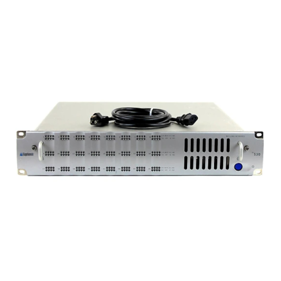
Power supply, ML530 840-07522-01 ML530 Manual The ML530 is packaged without cables. Sync, Control, MADI, and audio cables are required. 10 meter, 20 meter or custom length cable kits are available for order. See the ‘User Reference’ section. Safety and Precautions 1) Read Instructions - Read all the safety and operation instructions before operating the MC524 converters. -
Page 5: System Setup
THERE ARE NO USER SERVICEABLE PARTS IN THE ML530 System Setup The ML530 receives control information from the System 5 Interface Pilot via a 15 pin Dsub cable. All necessary connections to the ML530 are described in the cable specifications and hookup diagrams in this document. -
Page 6: Component Overview
Functional Description The ML530 Mic-Line Interface is a 24 channel digitally controlled analog preamplifier. Digital control of the ML530 is provided by the SC253i Interface Pilot which is under control of the system operator from the System 5 control surface. -
Page 7: Physical Specifications
Phase Phase invert (green) (currently not implemented) 12 dB attenuation (green) (currently not implemented) Power Switch On/Off button powers the unit up. Since the ML530 is digitally controlled via software, there are no other user controls on the front panel. ML530 Manual Version 1.0 Page 7... -
Page 8: Rear Panel Connectors
50 or 60Hz can be applied at this connector. Dimensions Height: 3.5 inches Width: 19 inches Depth: 18.6 inches Weight: 17 lbs Approximately 6 inches of depth should be left behind the ML530 for cable connections. ML530 Manual Version 1.0 Page 8 ©1999 Euphonix, Inc. -
Page 9: Technical Specifications
Low Z mode, 150ohm source) Common Mode Rejection (CMR): >50dB (10Hz – 30KHz) Phase Linearity: +/-10 degrees (20Hz – 70KHz) High Pass Filter: 80Hz 18dB/octave switched per channel Phase Invert: 180 degrees switched per channel ML530 Manual Version 1.0 Page 9 ©1999 Euphonix, Inc. -
Page 10: Environmental Requirements
Environmental Requirements 5 to 35 degrees Centigrade. Power Requirements 100-240 VAC, 50/60Hz. Power Consumption 100W ML530 Manual Version 1.0 Page 10 ©1999 Euphonix, Inc. -
Page 11: User Reference
User Reference ML530 Manual Version 1.0 Page 11 ©1999 Euphonix, Inc. -
Page 12: Ml530 Mic/Line Interface Cable Specification - Standard Configuration
User Reference ML530 Mic/Line Interface Cable Specification – Standard Configuration recommended locations Digital Core Machine Room Control Room AM713 Use relative locations to determine cable lengths ML530 Elco crimp pins and hoods for user inputs are supplied in accessory cable kits. Input cabling supplied by customer The standard lengths specified below are supplied so that the monitor interface can be located in the control room. -
Page 13: Ml530 Mic-Line Interface Hookup Diagram - Standard Configuration
ML530 Mic-Line Interface Hookup Diagram – Standard Configuration AM713 MADI MADI out to Studio Hub XLRFx12 to AES/EBU Sync In EM38x1 from Studio Hub Mic/Line Analog Elco crimp pins and hoods for user Control from 253i inputs are supplied in accessory... -
Page 14: Ml530 Mic-Line Interface Cable Specification - Optional Input Patch
ML530 Mic-Line Interface Cable Specification – Optional Input Patch recommended locations Digital Core AM713 Note: The patchbay in the patch option has the capacity to provide input patch to 48 channels or two ML530 Interfaces. An additional set of cable D is required for the second ML530 interface. -
Page 15: Ml530 Mic-Line Interface Hookup Diagram - Optional Input Patch
ML530 Mic-Line Interface Hookup Diagram – Optional Input Patch AM713 MADI MADI out to Studio Hub XLRFx12 to AES/EBU Sync In EM38x1 from Studio Hub Mic/Line Analog Control from 253i Interface Pilot EM38x1 to EM38x1 Patch to Mic/Line A - Optional Patchbay... -
Page 16: Input And Output Pinout Diagrams, Channels 1-12, Elco 38 Pin
ELCO 38 Pin Male Connector Seen From Rear (Insert pins from this side) Connector Specifications: 38-pin male w/ hood ELCO P/N 00-8016-038000-519 (Euph P/N 100-02099) Use crimp pins ELCO P/N 60-8017-031300-339 (Euph P/N 100-02100) ML530 Manual Version 1.0 Page 16 ©1999 Euphonix, Inc. -
Page 17: Input And Output Pinout Diagrams, Channels 13-24, Elco 38 Pin
ELCO 38 Pin Male Connector Seen From Rear (Insert pins from this side) Connector Specifications: 38-pin male w/ hood ELCO P/N 00-8016-038000-519 (Euph P/N 100-02099) Use crimp pins ELCO P/N 60-8017-031300-339 (Euph P/N 100-02100) ML530 Manual Version 1.0 Page 17 ©1999 Euphonix, Inc.
Need help?
Do you have a question about the ML530 and is the answer not in the manual?
Questions and answers