
Related Manuals for I-Gard SIGMA-MD


Summary of Contents for I-Gard SIGMA-MD
- Page 1 SIGMA-MD GROUND FAULT RELAY C-EG42EM Instruction Manual, December 2018 (Previously C-455EM)
-
Page 2: Table Of Contents
4.1 The SIGMA-MD Monitor Relay................6 4.2 Zero Sequence Current Sensor (ZSCS)..............7 4.3 Ngrs-XX Sensing Resistor..................8 4.4 Configuration of SIGMA-MD Monitor Relay and NGR ........8 5. Trip Relay and Auxiliary Fault Relay..................9 6. Led Indicators and Diagnostics....................10 6.1 Start-Up and Reset Indications................10 6.2 Power on Led (Green)....................11... - Page 3 ABOUT I-GARD I-Gard’s commitment to electrical safety provides both industrial and commercial customers with the products needed to protect their electrical equipment and the people that operate them. As the only electrical-safety focused company whose product portfolio includes neutral grounding resistors, high-resistance grounding systems and optical arc mitigation, we take pride in our technologies that reduce the frequency and impact of electrical hazards, such as arc flash and ground faults.
-
Page 4: General Information
(NGR) limiting the maximum NGR current to the relay’s set let through current. The SIGMA-MD monitor relay is designed to be used with a TxA type zero sequence current sensor, an NGRS-XX resistor sensor and an NGR sized to limit ground fault current to that stated in the installation’s specifications. -
Page 5: Description
NGR’s connection to the transformer neutral and the relay’s NGRS input terminal. The NGRS-XX resistor sensor is used by the SIGMA-MD monitor relay as part of a comparator to monitor the NGR resistance. The NGRS-XX resistor sensor contains a voltage suppressor which limits its output voltage to a safe level. -
Page 6: Neutral Grounding Resistor Monitoring
NGRS-XX resistor sensor and an NGR sized for a let-through current according to the specifications of the system in which it will be installed. DIP switches on the SIGMA-MD monitor relay are used to set the NGR let-through current to one of sixteen settings as shown in TABLE 7. -
Page 7: Installation Instructions
This setting can also be used to delay the indication by the SIGMA-MD monitor relay of a ground fault. The ground fault trip time is DIP switch selectable from its minimum setting of 40-to-60 milliseconds to 3.15 seconds. -
Page 8: Zero Sequence Current Sensor (Zscs)
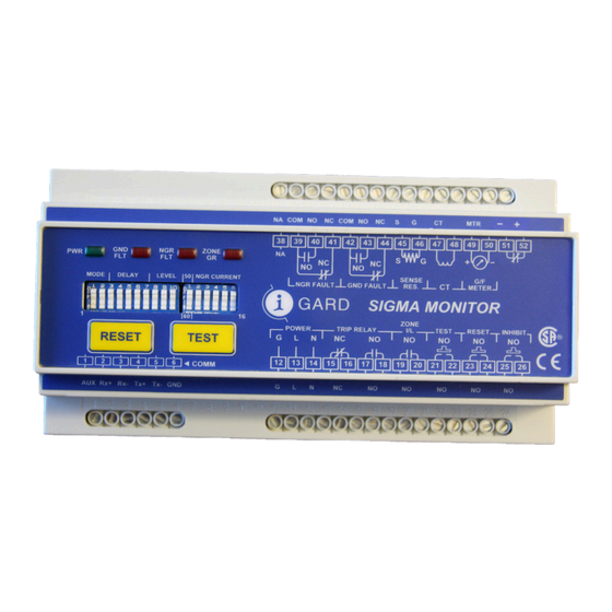
4.1.3 Connections Refer to Figure 2 for electrical connections to the SIGMA-MD monitor relay. Terminals on the relay will accept up to #14 AWG wire. Connect control power to terminals L and N. An isolation transformer is recommended as the source of supply to prevent excessive voltage being applied to the relay’s internal power supply. -
Page 9: Ngrs-Xx Sensing Resistor
Refer to Figure 2. The R terminal of the NGRS-XX resistor sensor must be connected to terminal 45 of the SIGMA-MD monitor relay as shown in Figure 2. The G terminal of the NGRS-XX resistor sensor should be connected to a suitable ground point. -
Page 10: Trip Relay And Auxiliary Fault Relay
• The ground fault auxiliary relay can be used to give local (door/panel) or remote indication of a ground fault. • The SIGMA-MD health monitor relay can be used to indicate the health status of the relay. If the SIGMA-MD loses power or if the SIGMA-MD processor fails, this normally closed relay will open. -
Page 11: Led Indicators And Diagnostics
When SIGMA-MD monitor relay is manually reset, the states of the trip relay and auxiliary fault relays are set to their respective idle states in the relay’s operating memory and are then stored in the non-volatile memory. -
Page 12: Power On Led (Green)
6.2 POWER ON LED (GREEN) / HEALTH MONITORING RELAY The Green PWR (Power) LED will be ON when control power is applied to the SIGMA-MD monitor relay and the relay is operating normally. The Green PWR (Power) LED will be FLASHING if control power is applied to the SIGMA- MD monitor relay but the relay is not operating correctly due to a malfunction in the microprocessor circuit. -
Page 13: Zone Ground Led (Red)
TEST push button on the front panel. The Red ZONE GR. LED will be turned ON while the installer is adjusting the operational settings on the SIGMA-MD monitor relay by way of the DIP switches. When the relay detects that the installer has stopped making adjustments to these settings the Red ZONE GR. -
Page 14: Relay Settings
8. RELAY SETTINGS All settings on the SIGMA-MD monitor relay are defined by means of a DIP Switch array located on the front panel of the relay. Refer to: • TABLE 1 for Trip Relay Operating Mode. • TABLE 2 for Trip Memory ON/OFF. -
Page 15: Trip Memory Setting
The trip relay will be energized (no-trip) if the SIGMA-MD monitor relay is reset through a local or remote reset. When reset, the SIGMA-MD monitor relay will resume monitoring of the system and, if a fault remains on the system, will detect the fault and will re-trip, de-energizing the trip relay. -
Page 16: Ground Fault Trip Current Level
20% when complying with this CSA Mine Safety Standard. 8.5 SYSTEM FREQUENCY The SIGMA-MD monitor relay has two settings for selecting the AC frequency of the system it monitoring for ground faults. Refer to TABLE 5 for DIP Switch settings for the AC frequency setting. - Page 17 * Idle state: See TABLE 1, TRIP RELAY OPERATING MODE SETTING for description of relay states when the SIGMA-MD relay is idle/not-tripped for failsafe and non-failsafe operating modes. Table 2 - Trip Memory Selection...
- Page 18 DIP switch #3 - #4 - #5 - #6 - #7 (left hand array) U = UP, D = DOWN G/F TRIP TIME DELAY DIP SWITCH SETTING (IN MILLISECONDS) 1050 1150 1250 1350 1450 1550 1650 1750 1850 1950 2050 2150 2250 2350...
- Page 19 Table 5- System Frequency Selection DIP switch #12 (right hand array) U = UP, D = DOWN NGR TOLERANCE % DIP SWITCH SETTING 66% to 300% 66% to 150% DOWN * * Recommended to be used with I-GARD NGR’s Table 6- NGR Tolerance Selection...
-
Page 20: Technical Specifications
U = UP, D = DOWN NGR LET-THROUGH DIP SWITCH SETTING ZSCS CURRENT (AMPERES) I-GARD TxA Type ZSCS I-GARD TxA Type ZSCS I-GARD TxA Type ZSCS I-GARD TxA Type ZSCS I-GARD TxA Type ZSCS I-GARD TxA Type ZSCS I-GARD TxA Type ZSCS... - Page 21 1 Form C (NO/NC) Rating: 10A @ 240V AC, 8A @ 24V DC, 1/2HP @ 240V AC SIGMA-MD Health Monitoring Relay Type: 1 Form A (NC) Rating: 1A @ 120V DC All relays are electrically held and are de-energized when control power is OFF.
- Page 22 65 mm (3•in.) The meter display is proportional to the measured current expressed as percentage of the set NGR let-through current. Note: A digital meter may be connected to instead of the I-GARD GFU-AM1, however it may required a separate power supply.
-
Page 23: Catalogue Numbers
5. Disconnect the control power leads from the SIGMA-MD monitor relay and ensure these conductors are insulated. 6. Connect short conductors between the L, N and G terminals of the SIGMA-MD monitor relay ensuring that the G terminal remains connected to ground. -
Page 24: Appendix B Can/Csa M421-00 Use Of Electricity In Mines (Excerpts)
60 s if the neutral-grounding device opens; and c. connected as close as practical to the supply neutral. 12. APPLICATION EXAMPLES Figure 1- Sigma-MD Monitor Relay Typical Installation Detail... - Page 25 Figure 2- Sigma-MD Monitor Relay Detail A Typical NGRS Sensing Resistor. Ngrs-6 (Dual Voltage) Model Shown. Figure 3- Low Voltage NGRS Resistor Sensor...
- Page 26 Figure 4- NGRS-25 Figure 5- NGRS-50...
- Page 27 Figure 6- High Voltage NGRS Resistor Sensors...
- Page 28 Phone: 905-673-1553 Fax: 905-673-8472 Toll Free: 1-888-737-4787 support@i-gard.com www.i-gard.com...
Need help?
Do you have a question about the SIGMA-MD and is the answer not in the manual?
Questions and answers