Table of Contents
Advertisement
Quick Links
Advertisement
Table of Contents

Summary of Contents for I-Gard mGARD-100
- Page 1 Ground fault relay C-419EM Instruction Manual, March 2015...
- Page 2 ABOUT I-GARD I-Gard’s commitment to electrical safety provides both industrial and commercial customers with the products needed to protect their electrical equipment and the people that operate them. As the only electrical-safety focused company whose product portfolio includes neutral grounding resistors, high-resistance grounding systems and optical arc mitigation, we take pride in our technologies that reduce the frequency and impact of electrical hazards, such as arc flash and ground faults.
-
Page 3: Table Of Contents
TABLE OF CONTENTS SUBJECT PAGE 1. Features ............................2 2. Introduction ............................. 2 3. Operation ............................3 3.1 Operation and Glossary of Terms ..................3 Auto Reset: ..........................3 Chassis Ground: ........................3 Interposing Current Sensor: ....................3 Failsafe: ............................. 3 Non-Failsafe: .......................... -
Page 4: Features
DIP switches. By double clicking the test/reset button on the unit, a functional test of the mGARD-100 is invoked. A single press of the remote test/reset button resets the relay after a trip. (It is not necessary to press the test/reset button to invoke... -
Page 5: Operation
• The ground fault trip current setting levels are higher than the 30 mA –12 Amp range available with the built-in 2” ZSCS. • The size of the power conductors on which the mGARD-100 is being applied is too large for the 2” built- in ZSCS. -
Page 6: Non-Failsafe
DIP switches be set at one time and before energizing the relay. Changes to the DIP switch settings when the mGARD-100 relay is energized may be performed without having any adverse effect on the relay. Table 3.0 displays all DIP switch selectable options. - Page 7 Table 3.0 mGARD-100 DIP switch settings (In the table above ‘R’ denotes right and ‘L’ denotes left switch function set to meaning Disabled Harmonic Filter Enabled Non-Failsafe Trip Contacts Failsafe Disabled Auto Reset Enabled Internal ZSCS 100:1 Interposing 1000:1 Interposing...
-
Page 8: Indication
The mGARD-SYM is a remote display indicator that is used in conjunction with I-Gard relays. The indicator has the capability to interconnect and work with up to 50 relays including the mGARD-100 relay in a bus network topology and provides detailed device status information. -
Page 9: Reset
It is NOT necessary to press the remote test/reset button after the ground fault has been cleared when the mGARD-100 is set in the pulsed trip auto reset mode. In this mode the relay will reset automatically in 3 seconds. -
Page 10: Installation Instructions
The internal electronics have been encapsulated in epoxy to improve the performance in high vibration environments. Try to keep the exposure to mechanical shock and vibration to a minimum and place the mGARD-100 in a clean dry enclosure. Locate the relay close to the isolating device (circuit breaker or contactor) that is protecting the circuit being monitored. -
Page 11: Built-In Current Transformer
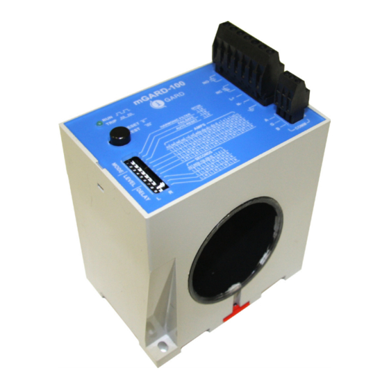
4.2 BUILT-IN CURRENT TRANSFORMER The mGARD-100 has a built-in current sensor (ZSCS) with 2.0” (50.8 mm) opening. The maximum continuous primary phase current is 250 Amps. Refer to Table 4.1 below to determine the cable sizes that will fit through the internal ZSCS. -
Page 12: Interposing Current Sensor
(T3A-S and T6A-S). The two secondary terminals of the external zscs are to be routed through the window of the mGARD-100. If using an mGARD-SYM, use the display to select the interposing I-Gard sensor that you are using to properly display current levels. - Page 13 Figure 4.2 shows an mGARD-100 relay operating in non-failsafe mode. The relay is monitoring the neutral conductor in a resistance grounded system. Figure 4.2: mGARD-100 relay monitoring a resistance grounded system and operating in failsafe mode. Figure 4.3 shows a system with several mGARD-100 relays monitoring branch circuits.
-
Page 14: Connections
In order to meet the Electromagnetic Compatibility (EMC) requirements a chassis bond is required between terminal 7 and the nearest ground point. This distance should be kept to a minimum. If the mGARD-100 is mounted on 35mm DIN rail, a DIN rail mounted ground terminal block can be installed beside the relay to act as the chassis ground point. -
Page 15: Technical Specifications
• A single Dual Pole Dual Throw (DPDT, 2 Form 1480V rms. for 1 minute C) relay for true failsafe operation. Ground Fault: Table 7.0 mGARD-100 timing with delay set to 20ms Pickup Settings: 30mA, 40mA, 60mA, 90mA, current delay (ms) when current... -
Page 16: Dimensional Drawings
I-GARD RESERVES THE RIGHT TO CHANGE SPECIFICATIONS OF ITS PRODUCTS WITHOUT NOTICE. 8. DImENSIONAL DRAwINGS Figure 8.0 mGARD-100 dimensions in millimetres (inches) - Page 17 NOTES...
- Page 18 905-673-1553 fax: 905-673-8472 toll free: 1-888-737-4787 sales@i-gard.com www.i-gard.com...


Need help?
Do you have a question about the mGARD-100 and is the answer not in the manual?
Questions and answers