Table of Contents
Advertisement
Advertisement
Table of Contents

Related Manuals for I-Gard MGFR Series


Summary of Contents for I-Gard MGFR Series
- Page 1 MGFR GROUND FAULT RELAY C-322EM Instruction Manual, March 2015...
- Page 2 ABOUT I-GARD I-Gard’s commitment to electrical safety provides both industrial and commercial customers with the products needed to protect their electrical equipment and the people that operate them. As the only electrical-safety focused company whose product portfolio includes neutral grounding resistors, high-resistance grounding systems and optical arc mitigation, we take pride in our technologies that reduce the frequency and impact of electrical hazards, such as arc flash and ground faults.
-
Page 3: Table Of Contents
TABLE OF CONTENTS SUBJECT PAGE 1. Introduction ..........................2 2. Description ..........................3 2.1 Catalogue Numbers ....................3 2.2 Pick-up Settings ......................3 2.3 Time-Current Characteristics .................3 2.4 Display ........................4 2.5 Trip Indicator ......................5 2.6 Reset Control ......................5 2.7 Button Functions .....................6 2.8 Power-On LED ......................8 2.9 Pre Trip Alarm ......................8 2.10 ZSIP ........................8 3. -
Page 4: Introduction
1. INTRODUCTION To provide a total solution and coordination with other devices, MGFR series relays range in trip levels from 10mA up to 1200A, in six versions. These versatile relays can be used in Solidly Grounded and Resistance Grounded systems. Too often, systems are protected with just one relay on the main service breaker, which leads to power interruption of the entire service if a ground fault occurs in any location. -
Page 5: Description
2.3 TIME-CURRENT CHARACTERISTICS Except in MGFR-1-ZB, MGFR-1-AB and MGFR-SE-ZB, all other models of MGFR series have two sets of defined trip characteristics. One is called Definite Minimum Time (DMT) and the other one is Inverse Definite Minimum Time (IDMT) characteristics. -
Page 6: Display
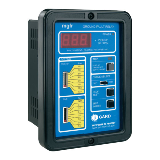
2.4 DISPLAY All models of the MGFR series have a three digit, numeric, LED display on the faceplate for indicating the fault current in per unit. The fault value at which a relay picks up is 1.00 per unit. Thus, in the above example, the relay should show ‘1.00’... -
Page 7: Trip Indicator
A green POWER indicator lights when the MGFR is energized with control power. Though the fault current is computed at approximately 2 msec intervals, the display is updated every 1 sec with the new value. If a sustained fault current value is less than 1.00 per unit, the relay will never trip and the value will be displayed for monitoring purposes. -
Page 8: Button Functions
2.7.1 SET FLASHING LEVEL AND FAULT CURRENT DISPLAY Fault current display feature is common to all models of the MGFR series. After a relay has tripped due to a ground fault, it keeps the last fault current value in internal memory. To see this value, in per unit, press the uppermost momentary pushbutton on the faceplate and release immediately. - Page 9 ASSOCIATED BREAKER TO TRIP unless the TRIP INHIBIT button is held down for the entire duration of the test. This feature is standard in all models of the MGFR series. However, the method of self test in MGFR-SE- ZB is different from the rest of the models.
-
Page 10: Power-On Led
TRIP RESET is operated (if manual RESET has been selected). 2.8 POWER ON LED A green LED on the faceplate of all the relays in the MGFR series indicates that the control power supply of the relay is ON. -
Page 11: Operation
3.3 MGFR-SE-ZB These relays are designed to operate with I-Gard Type RZ R=rectangular zero sequence sensors, all of which are electrically interchangeable. A test winding is built into each sensor and four screw type terminals are provided, two for the sensing winding (W1 and W2), and two for the SELF-TEST winding (R3 and R4). -
Page 12: Specifications
A single +5V DC source supplies power to all the electronics in the relay. 5. SPECIFICATIONS 5.1 SCOPE The specifications provided in this section cover all models of the MGFR series unless stated otherwise. 5.2 CONTROL POWER -ZB 120, 60 Hz, 15VA -AB 240, 50 Hz, 9VA 5.2.1 OPERATING VOLTAGE TOLERANCE... -
Page 13: Reset
5.6.3 METER ACCURACY (MEASURED MULTIPLE OF PICKUP) 0.2 X P.U. - P.U.: ±10% 1.2 X P.U. - 10 X P.U.: ±20% 10 X P.U. - 99.9 X P.U.: ±20%* * MGFR-20-ZB and MGFR-20-AB have measurement accuracies of ±20% from 10 x P.U. to 50 x P.U. 5.7 RESET Selectable - self Reset or Manual Reset by rear-connected jumper. -
Page 14: Installation
6. INSTALLATIONS 6.1 SITE REQUIREMENTS MGFR receives a current input signal from the secondary of one of the zero sequence sensors described in section 3. The sensor should be selected according to the busbar/conductor size and the model of MGFR being used. The sensor should be placed in the panel where the busbars/conductors are accessible. -
Page 15: Troubleshooting
Failure to trip on SELF TEST on -SE Types may result when the TEST current is not present, because of TEST winding connections, or control supply is not adequate (Should be 120V, 250 VA minimum). The self- test winding is only available on I-Gard type RZ sensors, therefore if any other types are used, the self-test will not work. - Page 16 If the trip contacts are used with AC shunt trip coils, there are various ways to suppress any counter EMF that might occur. The methods vary depending on applications, types of breaker used etc. Contact I-Gard if necessary. 7.2.7 UNIT TRIPS INSTANTANEOUSLY The MGFR will trip Instantaneously, without Time Delay, if the Factory supplied jumper is missing from the ZSIP OUT and ZSIP IN terminals at the rear of the unit.
-
Page 17: Table Of Figures Figure 1: Block Diagram Of Mgfr Relays
FIGURE 1: BLOCK DIAGRAM OF MGFR RELAYS... -
Page 18: Figure 2: Time - Current Characteristics
TIME-CURRENT CHARACTERISTICS FOR MGFR - 1-ZB, MGFR-2-ZB AND MGFR-20-ZB MGFR - 1-AB, MGFR-2-AB AND MGFR-20-AB FIGURE 2: TIME - CURRENT CHARACTERISTICS... -
Page 19: Figure 3: Time - Current Characteristics
TIME-CURRENT CHARACTERISTICS FOR MGFR - 200-ZB, MGFR-1200-ZB AND MGFR-SE-ZB MGFR - 200-AB AND MGFR-1200-AB FIGURE 3: TIME - CURRENT CHARACTERISTICS... -
Page 20: Figure 4: 3-Level Tcp And Zsip Connection
ZONE SELECTIVE INSTANTANEOUS PROTECTION (ZSIP) TIME CO-ORDINATED PROTECCTION (TCP) FIGURE 4: 3-LEVEL TCP AND ZSIP CONNECTION... -
Page 21: Figure 5: Connection Diagram For Mgfr Relays
FIGURE 5: CONNECTION DIAGRAM FOR MGFR RELAYS... -
Page 22: Figure 6: Connection Diagram For Mgfr-Se-Zb Relays
FIGURE 6: CONNECTION DIAGRAM FOR MGFR-SE-ZB RELAYS... -
Page 23: Figure 7 Outline & Mounting Dimensions For Mgfr Relays
FIGURE 7: OUTLINE & MOUNTING DIMENSIONS FOR MGFR RELAYS FIGURE 8: RECOMMENDED DIODE PROTECTION TO REDUCE SWITCHING SPIKES... - Page 24 Phone: 905-673-1553 Fax: 905-673-8472 Toll Free: 1-888-737-4787 sales@i-gard.com www.i-gard.com...
Need help?
Do you have a question about the MGFR Series and is the answer not in the manual?
Questions and answers