Table of Contents
Advertisement
Quick Links
Advertisement
Table of Contents

Subscribe to Our Youtube Channel
Related Manuals for Essence Smartcare Care@Home ES700IPD


Summary of Contents for Essence Smartcare Care@Home ES700IPD
- Page 1 Care@Home™ Indoor Photo Detector User Guide ESUGSC006 Version 1.0 September 2015...
- Page 2 If you do not agree with these terms, please do not access or use the remainder of this document. This document contains highly confidential information, which is proprietary to Essence SmartCare Ltd. and/or its affiliates (hereafter, "Essence"). No part of this document's contents may be used, copied, disclosed or conveyed to any third party in any manner whatsoever without prior written permission from Essence.
-
Page 3: Table Of Contents
Table of Contents Table of Contents Overview ..............................4 Installation Preparation .......................... 6 2.1. Required Equipment ........................6 2.2. Location Recommendations ...................... 6 Installation ............................. 8 3.1. Installing the IPD ........................8 3.2. “Walk Test” Mode ........................11 Installing Pet Immune Lens ........................12 4.1. -
Page 4: Overview
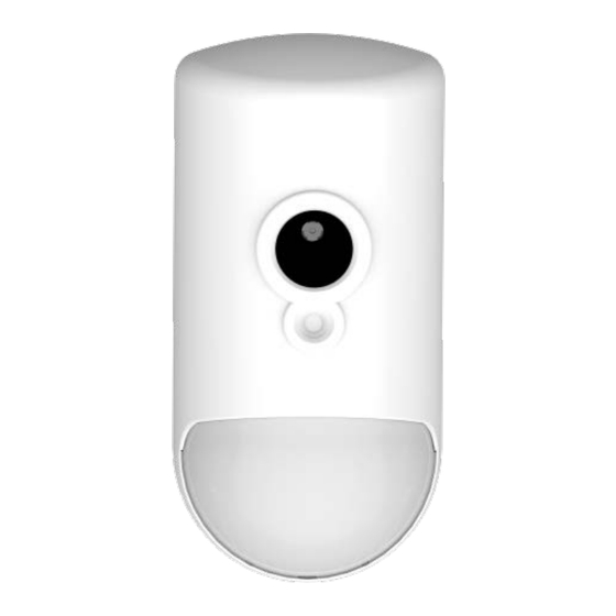
Overview 1. Overview The Essence Indoor Photo Detector (IPD) is a battery operated, bi-directional, wireless device combining the functionality of a Passive Infrared (PIR) motion detector with a high-resolution, full- color, JPEG-image-capturing camera. The IPD has the following features: Compressed photo-data sent via ECOP/RF protocol to the Care@Home Control Panel (CP) ™... - Page 5 Overview The IPD peripheral device model identification number is ES700IPD. NOTE: The images of batteries included in this User Guide are for illustration purposes only. Only batteries thoroughly tested and approved by Essence should be used to meet the device’s specifications. A list of the approved batteries and their specifications is provided in Table 2 on page 22.
-
Page 6: Installation Preparation
Installation Preparation 2. Installation Preparation The following are the steps and processes to prepare for the installation of the IPD. 2.1. Required Equipment Before beginning, prepare the following equipment: Double-sided mounting tape - provided. Three 1.5V AA alkaline batteries NOTE: To comply with the UL certification standards, use GP International Ltd. - Page 7 Installation Preparation Avoid wet, hot, and humid areas, such as a bathroom. Avoid facing sunlight or other light sources such as opposite a window. Care@Home™ Indoor Photo Detector User Guide...
-
Page 8: Installation
Installation 3. Installation The floor plan of the Resident’s premises determines the how and where to install the IPD. 3.1. Installing the IPD To install the IPD, perform the following procedure: 1. Identify the location for mounting the IPD, according to the criteria in section 2.2 on page 6. 2. - Page 9 Installation 4. Install the mounting-base with mounting-tape: Peel off the protective strips from the mounting-tape required for the installation location. Press the mounting-base into place. 5. If the IPD requires a Pet Immune Lens, install it now. For instructions on installing this lens, see chapter 4 on page 12.
- Page 10 Installation Figure 4: Battery Insertion When the batteries are installed, the LED in the lens compartment flashes Red, indicating that the IPD has powered up successfully. WARNING! A new battery can explode if it is incorrectly installed. Discard used batteries responsibly. Remember: To comply with the UL certification standards, use GP International Limited batteries.
-
Page 11: Walk Test" Mode
Installation Figure 5: Inserting the IPD with Lens Pointing Downward 3.2. “Walk Test” Mode A Walk Test is a function and signal verification check. The test is used to determine the detection area of the IPD. The Walk Test mode starts automatically after the IPD powers up, such as: ... -
Page 12: Installing Pet Immune Lens
Installing Pet Immune Lens 4. Installing Pet Immune Lens If the Resident has a pet, it is important to differentiate between the movement of the Resident and the movement of the pet. A pet immune lens can be installed to enable the IPD to ignore the pet’s movements. -
Page 13: Pet Immune Lens
Installing Pet Immune Lens Screws Figure 7: Unscrew the Screws 3. Detach the back cover from the front panel. The circuit board is attached to the inner compartment of the IPD back cover. Caution: When working within the inner compartment of the IPD, it is important to be careful not to damage the circuit board and other parts of the device. - Page 14 Installing Pet Immune Lens Figure 8: IPD Lens Latch Tabs 3. The outer lens should fall free of the IPD when the latch tabs are released. If the outer lens is not released, insert a dull thin object through the oval opening and gently push the outer lens and release it, as illustrated in Figure 9 below.
-
Page 15: Closing The Ipd
Installing Pet Immune Lens 5. Insert the outer lens in the groove surrounding the opening for the lenses, placing the outer lens on top of the pet immune lens, as shown in Figure 11 below. 6. Insert the latch tabs at the bottom center and at the side of the outer lens into the latch tab openings on the IPD opening for the lenses. - Page 16 Installing Pet Immune Lens 3. Attach the front panel to the back cover using the two screws. 4. Insert the batteries. 5. Return the IPD onto the mounting-base such that the lens is pointing downward. Figure 13: Align Holes for Screws Care@Home™...
-
Page 17: Operation
Operation 5. Operation The IPD is a passive device. The IPD must perform its detection functionality unhindered and with an unobstructed view of the coverage area. 5.1. IPD Physical Attributes Camera Lens DragonflyEye ™ lens LED Indicator Figure 14: IPD Physical Attributes The LED indicator is inside the IPD behind the lens. -
Page 18: Supervision
Operation For information about configuring the IPD parameters, see the Care@Home CMS User Guide for the ™ version of Care@Home ™ system installed on your Resident’s premises. 5.3. Supervision The IPD is a supervised device. The IPD periodically transmits its status, via an “I’m alive” message, to the CP. -
Page 19: Maintenance
Maintenance 6. Maintenance Maintenance of the IPD involves replacing batteries. 6.1. Replacing the Battery The battery status is reported automatically to the monitoring station via the CP. When the status indicates that the battery charge is low, the battery must be replaced. WARNING! A new battery can explode if it is incorrectly installed. - Page 20 Maintenance Figure 16: Open Battery Compartment Cover 3. Remove the old batteries. 4. Shake the IPD gently until you hear rattling sounds, confirming the release of residual circuit or energy. The rattling sound is the internal tamper-prevention mechanism. No damage has occurred to the IPD.
-
Page 21: Specifications
Specifications 7. Specifications Below are tables that list the technical specifications for the IPD and the approved batteries to use for the IPD. Table 1 below lists all the technical aspects and data about the IPD. Table 1: Device Technical Specifications Category Specifications Requirements... - Page 22 Specifications RF Coverage 700 m (2296 ft.) – Open Air Nominal Encoding 32-bit ID, over 4 billion combinations Functional Main MCU Advanced false alarm suppression algorithms Advanced gain temperature control Immunity Sealed PCB Multiple Detection Minimal time between detections: 2.5 minutes Mechanism NOTE: To reduce wireless traffic when the IPD...
-
Page 23: Appendix A Installation Method Alternatives
Installation Method Alternatives Appendix A Installation Method Alternatives The IPD can be mounted on a wall or in the corner of a room, using the mounting-base provided. The mounting-base is the back cover of the IPD, as shown in Figure 18 below. The back cover of the IPD Figure 17: The Mounting-Base There are two ways to install the IPD mounting-base:... - Page 24 Installation Method Alternatives Figure 18: Mounting-Tape on Back Cover The IPD can be installed using mounting-tape. The mounting-tape is approved for the following surfaces: Polycarbonate (PC) Aluminum Galvanized Steel Enameled Steel Stainless Steel Nickel Coated ABS ...
-
Page 25: Using Screws
Installation Method Alternatives Using Screws The mounting-base has eight holes, as shown in Figure 20 below, to allow for installation flexibility. Varying combinations of holes allows you to install the IPD either: Flat on a wall On an angle facing to the right ... -
Page 26: Installing The Ipd With Screws
Installation Method Alternatives Installing the IPD with Screws To install the IPD using screws, perform the following procedure: Figure 20: IPD Mounting-Base Screw Punch-outs 1. Release the IPD mounting-base by lifting the tab and pushing it forward, as illustrated in Figure 2 on page 8. -
Page 27: Appendix B Terms, Abbreviations, And Acronyms
Terms, Abbreviations, and Acronyms Terms, Abbreviations, and Acronyms Appendix B Table 3: Terms, Abbreviations, and Acronyms Description Term 3G is a short for 3 Generation. This is a term used to represent the 3rd generation of mobile telecommunications technology. Advanced Encryption Standard. A specification for the encryption of electronic data in a symmetric-key encryption format based on a design principle known as a substitution-permutation network, and is fast in both software and hardware. - Page 28 Terms, Abbreviations, and Acronyms Description Term Global System for Mobile Communications. A standard set developed by the European Telecommunications Standards Institute (ETSI). The GSM standard describes protocols developed for second generation (2G) digital cellular networks which are used by mobile phones. An Essence Term.
- Page 29 Terms, Abbreviations, and Acronyms Description Term Short Message Service Center. SMSC A cellular operator’s infrastructure for sending/receiving messages. When sending SMS messages, the user may connect directly to a provider’s infrastructure for this purpose. Simple Mail Transfer Protocol. SMTP An Internet standard for email transmission. Simple Object Access Protocol.
-
Page 30: Appendix C End User License Agreement And Terms & Conditions
The following terms will have the meaning ascribed to them in this Terms and Conditions: “The Company”: Essence SmartCare Ltd. “The System”: related social alarm product(s) and monitoring applications, products and solutions for home or any control systems or any part thereof. - Page 31 End User License Agreement and Terms & Conditions FILMED AND/OR STORED AND OR GATHERED BY THE SYSTEM (THE “VIDEO SEGMENTS”) (THE “INFORMATION” AND THE “VIDEO SEGMENTS” COLLECTIVELY TOGETHER: THE “SYSTEM INFORMATION”) IS STORED ON THE COMPANY'S AND/OR THE SERVICE PROVIDER SERVERS. THE SYSTEM INFORMATION INCLUDING THE VIDEO SEGMENTS IS THE SOLE PROPERTY OF THE COMPANY AND/OR THE SERVICE PROVIDER IN ACCORDANCE WITH THE AGREEMENTS BETWEEN THE COMPANY AND THE SERVICE PROVIDER.THE COMPANY SHALL HAVE ACCESS TO ALL OF THE SYSTEM INFORMATION AT COMPANY’S SOLE DISCRETION AND SHALL, FROM TIME TO TIME, AT THE REQUEST OF THE SERVICE PROVIDER FOR SUPPORT, MAINTENANCE, SYSTEM UPGRADES OR MODIFICATIONS AND ALIKE, REVIEW THE VIDEO SEGMENTS.
- Page 32 (ii) in case of emergency; or (iii) to a successor entity in connection with a merger, acquisition, bankruptcy or sale of all or substantially all of our assets. 5. Contacting Us If you have any concerns or questions about this Privacy Policy, please contact us at info@essence-grp.com. Copyright © 2015, Essence SmartCare Ltd., All rights reserved. Care@Home™ Indoor Photo Detector User Guide...
-
Page 33: Appendix D Care@Home™ System Terms Of Use
Care@Home™ System Terms of Use Appendix D Care@Home™ System Terms of Use In this Terms of Use (hereinafter the “ Terms of Use ”) the term “you or your” refers to the user of the System. The term “ Company ”... - Page 34 Care@Home™ System Terms of Use YOU EXPLICITLY ACKNOWLEDGE THAT THE SYSTEM IS NOT A MEDICAL OR LIFE SAVING DEVICE, SYSTEM; DOES NOT PROVIDE ANY MEDICAL, LIFE SAVING OR OTHERWISE PREEMPTIVE MEASURE AGAINST INJURY OR OTHERWISE BODILY HARM OR DEATH; NOR ASSUME IN ANY WAY TO REPLACE OR BE IN LIEU OF ANY SUCH.
- Page 35 4. Contacting Us If you have any concerns or questions about this Privacy Policy, please contact us at info@essence-grp.com. Copyright © 2015, Essence SmartCare Ltd., All rights reserved. Care@Home™ Indoor Photo Detector User Guide...
Need help?
Do you have a question about the Care@Home ES700IPD and is the answer not in the manual?
Questions and answers