Table of Contents
Advertisement
Quick Links
Advertisement
Table of Contents

Related Manuals for Yamasaki Y30 Series


Summary of Contents for Yamasaki Y30 Series
- Page 1 Y30 Series User Manual...
- Page 2 1 Copyright Information Copyright © 2019 belongs to Yamasaki Optical Technology Pty Ltd. Without agreement and written permission in advance from us, any content in the manual cannot be copied, saved for retrieval or spread by any means, including electronic or photocopying, recording or any other method.
- Page 3 Not taking any safety precautions or not following the instructions will violate the safety standards of design, manufacturing and application of these the OTDRs. In no case will Yamasaki bear the responsibilities for consequences incurred by violation of the following instructions.
- Page 4 Backward scattering is also the only effective way of connector inspection, which can be applied to measure the length of an optical fiber, too. Therefore, the Yamasaki OTDR ranges of products are a useful tool for optical fiber manufacturing, installation and maintenance.
-
Page 5: Table Of Contents
Contents Chapter I Overview ............................ 6 1 Instrument overview ..........................7 2 Instrument composition ........................7 3 Instrument panel ..........................8 Chapter II Main Operation Interface......................9 Chapter III Optical Time-domain reflectometer Module ................11 1 Main operation window ........................15 2 Event list window ........................... -
Page 6: Chapter I Overview
Chapter I Overview Instrument overview The Y30 Series OTDR is a testing instrument featuring high performance and multiple functions, that is designed for the FTTx network. It is used to measure such physical characteristics of optical fibers as the optic cable length, transmission loss and joint loss, accurate location of event points and failure points of an optical fiber link. -
Page 7: Instrument Composition
3 Instrument composition. Mainframe: Y30 Series optical time-domain reflectometer Standard configuration: Serial No. Name Remarks Power line and power adapter: an input voltage of Power line assembly 100~240V, 50~60Hz, an output voltage and an output current of 19V and 3.42A respectively at 2.0A... -
Page 8: Instrument Panel
3 Appearance Diagram of the OTDR Product 3.1 Front Panel... -
Page 9: Chapter Ii Main Operation Interface
Introduction to the Electrical Interface of the OTDR DC12V/3A Power supply interface Requirement to power supply interface: input DC12V/3A, polarity. USB SD Data Interfaces The OTDR is fitted with a, USB Type A , USB and Micro SD card interface. Charge Indicator When charging the battery the indicator is green. - Page 10 4 Introduction to the Home Page of the OTDR The Y30 Series optical time-domain reflectometer can be provided with such options as, an optical power meter, optical power source, VFL and Fibre Inspection Probe as required. 4-1. Operation Interface Diagram of the Home Page of the OTDR Click any of the OTDR, Optical power meter, Optical Power Source, VFL, Fiber Inspection Probe and help buttons to enter the corresponding operation interface to enable relevant functions.
-
Page 11: Chapter Iii Optical Time-Domain Reflectometer Module
5 Introduction to the OTDR 5.1 The measuring Purpose of the OTDR An OTDR displays the power of the returned signal related to distance. The information can be used to confirm the transmission quality of a fiber optic link. 5.1.1 Measuring Contents of the OTDR Position (distance) of event, result or fractured position of fiber optic link;... - Page 12 Distance calculation formula of the OTDR: Distance = (c/n) × (t/2) Among which: c= speed of light in vacuum (2.998 x 10⁸ m/s) t = Time delay between transmitted pulse and received pulse n = refractivity of optical fiber during testing process (nominated by manufacturer) When displaying the whole trace, each point on the trace graph represents the average value of several sampling points.
- Page 13 5.3.1 Initial Event “Initial event” on the OTDR trace is the event that marks the starting point of optical fiber. Under default conditions, “initial event” is located at the first event (usually it will be the first connector of the OTDR) of the tested optical fiber.
- Page 14 5.3.4 Non-reflection Event Non-reflection event brings loss on the whole transmission link of optical fiber, but no light reflection. On the curve, non-reflection event is shown as drop of optical power, as shown in Fig.6-3. Fig.6-3 Non-reflection Event 5.3.5 Event Inspection An OTDR sends an optical pulse into the optical fiber under inspection, then, begins to accept the returned optical signal immediately, and calculates the distance of an “event”...
-
Page 15: Main Operation Window
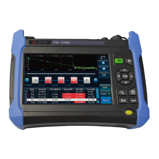
. Optical Time-domain reflectometer Module 1 Main operation window Click 【OTDR】 shown in Fig. 2-1 to enter the OTDR operation interface. The Y30 SERIES series OTDR testing interface is shown in Fig. 3-1: Fig. 6-1 Diagram of Y30 Series OTDR testing interface (1): Showing current system time, battery capacity. -
Page 16: Event List Window
(7): Menu bar. (8): Test condition display bar. Displaying such test conditions as current test range, wavelength, pulse width and test mode. (9): Name and saving time of the file read at present. It shows the name and saving time of the file read if current test curve is the one saved in the file read. -
Page 17: Graphical Analysis Window
(2) No.: Number of current event. (3) Distance (km): Distance between current event point and reference origin point. (4) Attenuation (dB/km): Average loss of the optical fiber section ahead of current event point. (5) Loss (dB): Connection loss measured at current event point. * It indicates the connection loss measured currently is bigger than the set critical threshold of the connection loss. -
Page 18: Overview Of Main Menu Structure And Functions
Meaning of each graph in the graphical analysis window is shown below: : Indicating the event point can be the optical fiber start point. : Indicating the joint meets the pass-through condition. : Indicating the joint connection loss exceeds the threshold, failing to meet the pass-through condition. -
Page 19: Usage
Functions of all buttons on the menu bar are shown below: 【Avg.】: It is used to control the OTDR progressive average of the average times set against the lost curve tested; after test, the contents shown on the button changes automatically from 【Stop】 to 【Avg.】, and the OTDR test stops at the same time. - Page 20 Fig. 3-5 Window of setting Y3 SERIES70 OTDR test conditions 5.1Testing optical fiber link The operation steps are shown as follows: Select the test wave length. Set such test conditions as the test mode. Clean the optical fiber to be tested. Connect the optical fiber to be tested to corresponding OTDR fiber output port.
- Page 21 If the OTDR test mode is set to manual: Click 【Real Time】 in the main menu bar (and 【Real Time】 is changed to 【Stop】 at this time) to conduct sweep test on the optical fiber link under test in real time as per the test conditions set at present, and refresh the test curve in the main operation window continuously.
- Page 22 Lock Cursors A&B: Select it to lock the distance between cursors A&B. After that, to move any cursor is to move the other together, with the distance between them keeping unchanged. Otherwise, when one of the cursors is moved, the other one will not move. High resolution test: Select it to rise the sampling points of the instrument to 256k, improving the resolution capability on short-distance events occurred on the optical fiber link under test.
- Page 23 average loss of optical fiber measured optical fiber length accurately. b. Clean the connector of the optical fiber the optical fiber b. Too long trailing at the front under test or add a little matching solution, measured end of the test curve and then test the curve again.
- Page 24 Test the curve again with big attenuation with current pulse width set (select the average test mode and set certain average times in this case). Event points are too close with each other in the test curve. In case of any adjacent event points being omitted, try to solve the problem as follows: Test the curve again with small pulse width (select the average test mode and set certain average times in this case).
-
Page 25: Chapter Iv Working Principles
Appendix A Cleaning the optical output port Chapter IV Working Principles 1 Working Principles During optical transmission via the optical fiber, small changes in optical fiber refractive index can result in rayleigh scattering, and refractive index saltation on the end face or failure point of the optical fiber can result in Fresnel reflection. -
Page 26: Chapter V Technical Parameters
Appendix B Technical specifications for various OTDR standard modules Chapter V Technical Parameters 1 General features General features of the Y3 SERIES70 optical time-domain reflectometer are as follows: NAME CONTENTS Display 800×480 and 7” TFT color LCD (provided with standard capacitive touch screen, with the resistance touch screen as an option) 0.4, 0.8, 1.6, 3.2, 8, 16, 32, 64, 128, 256 and 512(single-mode, multi-mode 1300nm)... -
Page 27: Main Technical Indicators
Appendix B Technical specifications for various OTDR standard modules functions Test the optical fiber or cable length. Test the distance between any two points on the optical fiber curve. Test and display the loss between any two points on the optical fiber curve as well as the optical fiber attenuation constant. -
Page 28: Annex A Cleaning The Optical Output Port
Appendix B Technical specifications for various OTDR standard modules 3.3 Optical power meter function (optional) (1) Wavelength range: 1200nm ~ 1650nm; (2) Power range: -60dBm ~ 0dBm; (3) Power test uncertainty at the calibration point: better than 0.22dB (-25dBm, CW and 1310/1550nm);... -
Page 29: Annex B Technical Specifications For Various Otdr Standard Modules
Appendix B Technical specifications for various OTDR standard modules Tools for cleaning the optical output port and connector Use such tools as the fiber cleaner and cleaning rod to clean the optical output port and connector. Otherwise, prepare as follows: A cotton bud doped in isopropyl alcohol. -
Page 30: Annex C Remote Control Command Set
Annex C Remote control command set Command type Function Command Starting measurement Wavelength Measurement parameters (distance, pulse width and sampling mode) Sampling time Refractive index Command explanation Description Starting measurement Command LD□1 1: Start measurement Description Set wavelength Command WLS□<Wavelength>1310/1550/1625 <Wavelength>:Unit: nm(See the module number in the product manual for wavelength available)... - Page 31 3200: 3.2km 8000: 8km 16000: 16km 32000: 32km 64000: 64km 128000: 128km 256000: 256km 512000: 512km <Pulse width mode>: 0: Manual setting <Pulse width>: Pulse width level: 3ns, 5ns, 10ns, 30ns, 80ns, 160ns, 320ns, 640ns, 1280ns, 5120ns, 10240ns and 20480ns <Sampling mode>: 0:Speediness 1: Accuracy...
- Page 32 Description Set sampling time Command ALA□<Mode>, <Setting> <Mode>: Average mode. 0:Time(s) <Setting>: If the mode is time(s), the range can be set to 1-9999. Description Set the refractive index Command IOR□<Refractive index> <Refractive index>: The range is 1.300000 – 1.800000.
- Page 33 Yamasaki OTDR Software This is the updated, English version of the software (zip file) and the “Instructions for simulation analysis of OTDR” (pdf) unzip the file by double clicking on it – finalOTDRx86 will appear. Step 1: Double click on this The following will appear on your screen Find OTDR Application and double left click on it.
- Page 34 The following prompt should appear on your screen Click on - Extract all Select a destination and click on Extract Click on OTDR to run the program.
- Page 35 Step 2: The software should load, and the program should be able to be used, however You may possibly encounter the following hurdles due to antivirus software protection Click on more info Click on Run anyway Click on OK...
- Page 36 Click on close and Open the OTDR application again The screen will look like this once you have opened a file into the software. Congratulations! You have successfully installed the new, updated OTDR Software.
Need help?
Do you have a question about the Y30 Series and is the answer not in the manual?
Questions and answers