Table of Contents
Advertisement
Quick Links
Temperature Monitoring Unit for Transformers and
Other Electrical Machines
DQ61
User Manual
(Hardware Rel. 2.0 - Firmware Rel. 1.3.3)
http:
www.quanta.it
http:
www.quantasrl.eu
e-mail:
acquisti@quanta.it
contabilita@quanta.it
ufficiotecnico@quanta.it
P.E.C.:
quanta@pec.quanta.it
Rev 01.14_en
28/12/2012
Advertisement
Table of Contents

Summary of Contents for QUANTA DQ61
- Page 1 P.E.C.: quanta@pec.quanta.it Temperature Monitoring Unit for Transformers and Other Electrical Machines DQ61 User Manual (Hardware Rel. 2.0 - Firmware Rel. 1.3.3) Rev 01.14_en 28/12/2012...
-
Page 2: Table Of Contents
General Information _______________________________________________________________ 3 How to use this manual ____________________________________________________________ 3 Identification Data ________________________________________________________________ 4 The DQ61 ______________________________________________________________________ 4 Terms and conditions of intended use ____________________________________________ 4 Conditions of use not permitted _________________________________________________ 5 Technical specifications _______________________________________________________ 6 Funzionamento e uso _____________________________________________________________ 7... -
Page 3: General Information
This manual should be considered part of the unit, consequently it shall always be available for consultation by the management and maintenance staff. Keep it with care; in case of loss or damage you may request a copy asking your dealer or directly QUANTA S.r.l. quoting the model and serial number of the device, Via A. -
Page 4: Identification Data
4 The DQ61 Terms and conditions of intended use The DQ61 is an electronic control unit, designed to be used to monitor and control the temperature of electrical machines, e.g. medium/high voltage transformers or electrical motors. Since it is not possible to know in advance what are the real application conditions in which the device will be utilized, and given the great variability of the fields of application, it is responsibility of the user to determine the suitability of DQ61 in perform properly the specific application. -
Page 5: Conditions Of Use Not Permitted
Conditions of use not permitted The use of DQ61 in areas classified in category 20, 21 or 22 and / or 0, 1, 2 according to EU Directive 94/9, called Atex, is expressly prohibited. ... -
Page 6: Technical Specifications
P.E.C.: quanta@pec.quanta.it 4.3 Technical specifications Universal 90-250Vac 50-60Hz and 16…26Vcc/ac, 7VA Power supply N°4 RTD Pt100 – 3 wires Available inputs Cable lengts compensation Up to 500m (0.5 mm External connections Terminals wiring up to AWG 17 for Pt100, up to AWG14 for power and relays -20 …... -
Page 7: Funzionamento E Uso
During programming it guides the user to setup the parameters. Located at the bottom of the display, it shows the operating Status Row condition of the DQ61, alarm conditions particularly. The A1 LED indicates that the cooling fan is ON. The A2 LED indicates an alarm condition. -
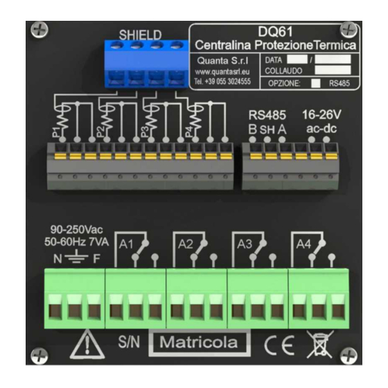
Page 8: Rear Panel
On the secondary of large transformers may be present very strong transient disturbances, which might exceed the filters and safeguards built into DQ61 and destroy it; for this reason it is advisable to power it by a transformer 24VAC or 24VDC power supply. If the power is taken directly from the secondary of the transformer to be protected, fit a suitable additional filter. -
Page 9: Pt100 Probes Electrical Connections
P4 measures the temperature of the magnetic core. See the diagram below: Pt100 P4 Pt100 Pt100 Pt100 DQ61 Figure 5 5.6 Other electrical connections Connect the low safety voltage power supply to terminals 21 and 22 or connect the mains supply to terminals 23, 24 and 25. -
Page 10: Buzzer Features
Pulse mode: It is activated for a predetermined time and then returns to the rest condition. The relay A4 (indicated by LED FAULT) is always on and going off to signal a DQ61 fault condition or a fault condition in one or more probes. -
Page 11: Programming
after the row The row can be reached by pressing the key If no operations are done on the keyboard for about 30 seconds, DQ61 autonomously back to normal view. 6.2.1 MAX TEMPERATURE RECORD Menu twice, you can reset the recorded This menu shows the maximum temperatures recorded. -
Page 12: Alarm Setting Menu
P.E.C.: quanta@pec.quanta.it 6.2.2 ALARM SETTING Menu This menu shows the temperature set point for fan, alarm and tripping. The settings are common to the probes and P1, P2 and P3, while P4 probe has a setting dedicated. By pressing the keys you place the cursor on point;... -
Page 13: Display Mode Menu
P.E.C.: quanta@pec.quanta.it 6.2.4 DISPLAY MODE Menu and This menu allows you to set the screen to normal working mode, as it may be needed. Pressing the keys you place the cursor on the screen that you want; pressing the key twice, you select and confirm the choice. -
Page 14: User Menu
Sets the hysteresis on the alarm temperature between 1 and 20 °C (default 5 °C). For example, if a given alarm threshold is set to 120 °C and the hysteresis at 5 °C, DQ61 signal an alarm when the temperature exceeds 120 °C and will continue to report it until the temperature drops below 115 °C... -
Page 15: Service Menu
P.E.C.: quanta@pec.quanta.it This feature allows you to use the DQ61 to monitor only 3 temperatures without being warned for failure or absence of the fourth probe. Sets the menu language choosing among ITALIAN, ESPANOL, FRANCAIS, ENGLISH. 6.2.6 SERVICE Menu MENU, MENU, MENU, ,... - Page 16 This condition is indicated on the status line with the message “Alarms probe T1 OFF”. The parameters from P14 to P17 allow you to use DQ61 with a number of probes between 1 and 4 without having to worry about the alarms generated by the probes that may be missing.
-
Page 17: Instrument Info
P.E.C.: quanta@pec.quanta.it Default 19.200. (Allowed values: between 1.200 and 38.400 baud). If the RS485 MODBUS option is not installed, the value indicated is and will not be editable. Choice of unit between °C and °F. -
Page 18: Remote Control
P.E.C.: quanta@pec.quanta.it 7 Remote Control Through the RS485 port (when the corresponding option board is installed) DQ61 can be controlled by an External manager communicating with MODBUS protocol. 7.1.1 Communication: Physical Layer Asynchronous serial communication, half-duplex, 19200bps (default), 8 data bit (LSB first), even parity, 1 stop- bit. - Page 19 P.E.C.: quanta@pec.quanta.it CHAR – alphanumeric character (0 ÷ 255) BYTE – 8-bit positive integer (0 ÷ 255) WORD – 16-bit positive integer (0 ÷ 65535) BITMAP – 16-bit words corresponding to 16 flags in order from 0 to 15 (for each bit logic is: 0 = off, 1 = ...
-
Page 20: Monitorable And Editable Registers Table
P.E.C.: quanta@pec.quanta.it 7.2 Monitorable and Editable Registers Table 7.2.1 Monitorable and Editable Parameters and Variables Address Type Description 0x0000 BITMAP Bitmap configuration flag: Bit0. Default configuration Bit1. TRIP latch Enabled Bit2. Probe T1 Enabled Bit3. -
Page 21: Read-Only Registers Table
P.E.C.: quanta@pec.quanta.it 7.3 Read-Only Registers Table 7.3.1 Read-Only Variables Address Type Description 0x8000 WORD Firmware Release: Bit15÷11 – Version number Bit10÷6 – Revision number Bit5÷0 – Build number 0x8001 Temperature T1 (°C o °F) 0x8002 Temperature T2 (°C o °F) -
Page 22: Overall Dimensions
In the event of unexpected behavior, before concluding that the unit is faulty, check the following list: Symptom Cause and / or remedies The DQ61 not turn on Make sure there is voltage at the power supply terminals. Make sure the power connector is properly inserted in its place.
Need help?
Do you have a question about the DQ61 and is the answer not in the manual?
Questions and answers