Table of Contents
Advertisement
Advertisement
Table of Contents

Related Manuals for Orange Pi Zero2


Summary of Contents for Orange Pi Zero2
- Page 1 Orange Pi Zero 2 User Manual...
-
Page 2: Table Of Contents
1.3. Who’s it for?.........................3 1.4. Hardware Specification of Orange Pi Zero 2...............4 1.5. Top and bottom views of Orange Pi Zero 2.................5 1.6. Orange Pi Zero 2 interface details..................6 2. Introduction to the use of the development board................7 2.1. - Page 3 3.15.1. Connect mouse or keyboard test................44 3.15.2. Connect USB storage device test................44 3.16. USB camera test.......................45 3.17. 13 Pin transfer board interface pin description..............47 3.18. Audio test..........................48 3.18.1. Headphone jack play audio test................48 3.18.2. HDMI audio playback test..................50 3.19.
-
Page 4: Basic Features Of Orange Pi Zero 2
Who’s it for? 1.3. Orange Pi Zero 2 is for anyone who wants to start creating with technology – not just consuming it. It's a simple, fun, useful tool that you can use to start taking control of the world around you. -
Page 5: Hardware Specification Of Orange Pi Zero 2
Hardware Specification of Orange Pi Zero 2 1.4. Hardware Specification Allwinner H616 64-bit 1.5GHz high-performance Quad-core Cortex- A53 processor Mali G31 MP2 Supports OpenGL ES 1.0/2.0/3.2、OpenCL 2.0 Memory(SDRAM) 512MB/1GB DDR3 (Shared with GPU) Onboard Storage MicroSD card slot、2MB SPI Flash... -
Page 6: Top And Bottom Views Of Orange Pi Zero 2
Top and bottom views of Orange Pi Zero 2 1.5. Top view Bottom view:... -
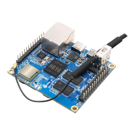
Page 7: Orange Pi Zero 2 Interface Details
Orange Pi Zero 2 interface details 1.6. -
Page 8: Introduction To The Use Of The Development Board
1) MicroSD card, a high-speed card above class 10 with a minimum capacity of 8GB, it is recommended to use SanDisk’s MicroSD card. Orange Pi uses SanDisk’s MicroSD card with all the tests. Other brands of TF cards may cause the OS to fail to start. - Page 9 5) 13-Pin expansion board The expansion board is as shown in the following picture b. The 13-Pin header on the Orange Pi Zero 2 development board can be connected to an expansion board to expand the functions that are not on the development board.
- Page 10 6) USB mouse and keyboard, as long as it is a standard USB mouse and keyboard, the mouse and keyboard can be used to control the Orange Pi development board 7) IR remote control mainly used to control the Android OS...
-
Page 11: Download The Image And Relevant Documents
function, you need USB to TTL module and DuPont cable to connect the development board and the computer 11) A personal computer with Ubuntu and Windows operating OS Ubuntu14.04 PC Optional, used to compile Android source code Ubuntu18.04 PC Optional, used to compile Linux source code Windows PC Used to flash Android and Linux images Download the image and relevant documents... -
Page 12: Method To Flash Linux Image To Microsd Card Based On Windows Pc
d. Official tools: mainly include the software needed during the use of the development board Android image: saved on Baidu Cloud Disk and Google Cloud Disk Ubuntu image: saved on Baidu Cloud Disk and Google Cloud Disk g. Debian image: saved on Baidu Cloud Disk and Google Cloud Disk Method to flash Linux image to MicroSD card based on 2.3. - Page 13 OK 4) Download the Linux operating OS image file compression package you want to flash from download page of the Orange Pi official website, and then use the decompression software to decompress it. In the decompressed file, the file ending with ".img"...
-
Page 14: Method To Flash Linux Image To Microsd Card Based On Ubuntu Pc
After the image is written, click the "Exit" button to exit, and then you can pull out the MicroSD card and insert it into the development board to boot Method to flash Linux image to MicroSD card based on 2.4. Ubuntu PC 1) First, prepare a Micro card with 8GB or larger capacity. - Page 15 6) Download the Linux operating OS image file compression package you want to burn from the Orange Pi data download page, and then use the decompression software to decompress it. In the decompressed file, the file ending with ".img" is the operating OS image file.
-
Page 16: Method Of Flashing Android Firmware To Microsd Card
9) The writing process will prompt the writing speed and remaining time 10) After burning, the following interface will be displayed, then you can unplug the MicroSD card from the computer and insert it into the development board to start Method of flashing Android firmware to MicroSD card 2.5. - Page 17 SanDisk. 2) Then use a card reader to insert the MicroSD card into the computer 3) Download the Android 10 OS and PhoenixCard flashing tool from Orange Pi's data download page. Please make sure that the PhonenixCard tool version is PhonenixCard-v4.2.3.
- Page 18 MicroSD card 8) Then start to write the Android OS to MicroSD card First, select the path of the Android image in the "Image" column b. Select "Start up" in "Type of Making Card" Then click the "Burn" button to start burning...
-
Page 19: Start The Orange Pi Development Board
TV or HDMI display through a Micro HDMI to HDMI cable 3) Connect the USB mouse and keyboard to control the Orange Pi development board 4) The development board has an Ethernet port, which can be plugged into the... -
Page 20: How To Use The Debug Serial Port
1) First, you need to prepare a USB to TTL module. This module can be bought in Orange Pi stores. If there are other similar USB to TTL modules, you can also insert the USB end of the USB to TTL module into the USB port of the computer... -
Page 21: How To Use The Debug Serial Port On The Ubuntu Platform
2.7.2. How to use the debug serial port on the Ubuntu platform? 1) If the USB to TTL module is connected normally, you can see the corresponding device node name under /dev of Ubuntu PC, remember this node name, you will use it when setting up the serial port software later test@test:~$ ls /dev/ttyUSB* /dev/ttyUSB0... - Page 22 6) First, select the setting interface of the serial port 7) Then set the parameters of the serial port a. Set the Serial line to connect to /dev/ttyUSB0 (modify to the corresponding node name, generally /dev/ttyUSB0) b. Set Speed(baud) to 115200 (baud rate of the serial port) c.
-
Page 23: How To Use The Debug Serial Port On The Windows Platform
9)After starting the development board, you can see the Log information output by the OS from the opened serial terminal 2.7.3. How to use the debug serial port on the Windows platform? 1) Many serial debugging tools that can be used under Windows, such as SecureCRT, MobaXterm, etc. - Page 24 Then choose to download the Home version d. Then select the Portable version. After downloading, you don’t need to install it, you can open it directly 3) After downloading, use the decompression software to decompress the downloaded compressed package, you can get the executable software of MobaXterm, and then double-click to open it...
- Page 25 4) After opening the software, the steps to set the serial connection are as follows a. Open the session setting interface b. Select the serial port type c. Select the port number of the serial port (choose the corresponding port number according to the actual situation), if you cannot see the port number, please use the 360 driver master to scan and install the driver for the USB to TTL serial chip d.
-
Page 26: Linux Os Instructions
Debian 10 linux4.9 Support Support 3.2. linux4.9 kernel driver adaptation status Orange Pi Zero 2 currently only supports the linux 4.9 version of the kernel, and the driver adaptation is shown in the table below Function Status HDMI video HDMI Audio USB2.0 x 3... -
Page 27: Instructions For The Automatic Login Of Linux Desktop Version Os
Kernel boot to enter system bright Turn off GPIO port PC13 PC12 Instructions for the automatic login of Linux desktop 3.5. version OS 1) The desktop version of the OS will automatically log in to the desktop after it is started by default, without entering a password 2) Modify configuration... -
Page 28: Start The Rootfs In The Auto-Expanding Tf Card For The First Time
1) The log level of the Linux OS is set to 1 by default. When using the serial port to view the startup information, the kernel output log is as follows, basically all shielded Starting kernel ... Uncompressing Linux... done, booting the kernel. Orange Pi 2.0.8 Bionic ttyS0 orangepi login:... -
Page 29: Ethernet Port Test
2) When there is a problem with the OS startup, you can use the following method to modify the value of log level, to print more log information to the serial port display, which is convenient for debugging root@orangepi:~# sed -i "s/verbosity=1/verbosity=7/" /boot/orangepiEnv.txt root@orangepi:~# sed -i "s/console=both/console=serial/"... -
Page 30: Ssh Remote Login Development Board
64 bytes from 14.215.177.38 (14.215.177.38): icmp_seq=3 ttl=56 time=6.26 ms 64 bytes from 14.215.177.38 (14.215.177.38): icmp_seq=4 ttl=56 time=7.27 ms --- www.a.shifen.com ping statistics --- 4 packets transmitted, 4 received, 0% packet loss, time 3002ms rtt min/avg/max/mdev = 6.260/6.770/7.275/0.373 ms SSH remote login development board 3.9. -
Page 31: Ssh Remote Login Development Board Under Windows
You can enter the following command on the development board and try to connect root@orangepi:~# rm /etc/ssh/ssh_host_* root@orangepi:~# dpkg-reconfigure openssh-server 3.9.2. SSH remote login development board under Windows 1) First, get the IP address of the development board 2) MobaXterm can be used to remotely log in to the development board under windows, first create a new ssh session a. -
Page 32: Hdmi Display Test
HDMI display test 3.10. 1) Use Micro HDMI to HDMI cable to connect Orange Pi development board and HDMI display 2) If the HDMI display has image output after starting the Linux OS, it means that the HDMI interface is working normally HDMI resolution setting 3.11. -
Page 33: How To Modify The Width And Height Of Framebuffer
console=both disp_mode=1080p60 2) The disp_mode variable supports setting values as shown in the following table disp_mode supported value HDMI Resolution HDMI refresh rate 480i 720x480 576i 720x480 480p 720x480 576p 720x576 720p50 1280x720 720p60 1280x720 1080i50 1920x1080 1080i60 1920x1080 1080p24 1920x1080 1080p50 1920x1080... - Page 34 b. HDMI resolution is 1080p60, fb0_width and fb0_height are 1280x720 display HDMI resolution is 1080p60, fb0_width and fb0_height are 720x576...
-
Page 35: Wifi Connection Test
d. HDMI resolution is 1080p60, fb0_width and fb0_height are 720x480 display WIFI connection test 3.13. 3.13.1. Test method of Linux server version image 1) Log in to the Linux OS first, there are three ways a. If the development board is connected to the network cable, you can log in to the Linux OS remotely via SSH b. - Page 36 c. If you connect the development board to the HDMI display, you can log in to the Linux OS through the HDMI display terminal 2)Then enter nmtui in the command line to open the wifi connection interface root@orangepi:~# nmtui 3)Enter nmtui to open the interface as shown below 4)Select Activate a connect and press Enter 5)Then you can see all the searched WIFI hotspots...
- Page 37 6)Select the WIFI hotspot you want to connect to, then use the Tab key to position the cursor on Activate and press Enter 7)Then a dialog box for entering the password will pop up, enter the corresponding password in Password and press Enter to start connecting to WIFI 8)After the WIFI connection is successful, a "*"...
-
Page 38: Test Method Of Linux Desktop Version Image
9)The wifi IP address can be viewed through the ifconfig command root@orangepi:~# ifconfig wlan0 wlan0: flags=4163<UP,BROADCAST,RUNNING,MULTICAST> mtu 1500 192.168.1.49 inet netmask 255.255.255.0 broadcast 192.168.1.255 inet6 fe80::76bb:f67d:ef98:2f9a prefixlen 64 scopeid 0x20<link> ether 12:81:3e:a8:58:d8 txqueuelen 1000 (Ethernet) RX packets 185 bytes 109447 (109.4 KB) RX errors 0 dropped 61 overruns 0 frame 0 TX packets 27 bytes 14783 (14.7 KB) TX errors 0 dropped 0 overruns 0 carrier 0 collisions 0... - Page 39 2) Click More networks in the pop-up drop-down box to see all scanned WIFI hotspots, and then select the WIFI hotspot you want to connect to 3) Then enter the password of the WIFI hotspot, and then click Connect to start connecting to WIFI 4) After connecting to the WIFI, you can open the browser to check whether you can...
-
Page 40: How To Use Bluetooth
surf the Internet. The entrance of the browser is shown in the figure below 5) After opening the browser, if you can see the page of the OrangePi website, or you can open other web pages, the WIFI connection is normal How to use Bluetooth?... - Page 41 Then select the adapter 3) Set Visibility Setting to Always visible in the Bluetooth adapter setting interface, and then click close to close 4) Then open the configuration interface of the Bluetooth device 5) Click Search to start scanning surrounding Bluetooth devices...
- Page 42 6) Then select the Bluetooth device you want to connect to, and then click the right mouse button to pop up the operation interface of the Bluetooth device. Select Pair to start pairing. Here is a demonstration of pairing with an Android phone 7) When pairing with a mobile phone, a pairing confirmation box will pop up in the upper right corner of the desktop, select Confirm to confirm.
-
Page 43: How To Use The Server Version Image
9) The interface for sending pictures is as follows 3.14.2. How to use the server version image? 1) When the linux OS starts, the aw859a-bluetooth.service service will be run to initialize the Bluetooth device. After entering the OS, you can use the hciconfig command to check whether there is a Bluetooth device node. - Page 44 Link mode: SLAVE ACCEPT Name: 'orangepizero2' Class: 0x000000 Service Classes: Unspecified Device Class: Miscellaneous, HCI Version: 5.0 (0x9) Revision: 0x400 LMP Version: 5.0 (0x9) Subversion: 0x400 Manufacturer: Spreadtrum Communications Shanghai Ltd (492) 2) Use bluetoothctl to scan for Bluetooth devices root@orangepi:~# bluetoothctl [NEW] Controller 10:11:12:13:14:15 orangepizero2 [default] Agent registered...
-
Page 45: Usb Interface Test
USB interface test 3.15. 3.15.1. Connect mouse or keyboard test 1) Insert the keyboard of the USB interface into the USB interface of the Orange Pi development board 2) Connect the Orange Pi development board to the HDMI display 3) If the mouse or keyboard can operate normally, the USB interface is working normally (the mouse can only be used in the desktop version of the OS) 3.15.2. -
Page 46: Usb Camera Test
29G 208K 29G 1% /mnt USB camera test 3.16. 1) First insert the USB camera into the USB port of the Orange Pi development board 2) Then through the lsmod command, you can see that the kernel has automatically loaded the following modules... - Page 47 /etc/init.d/motion restart [ ok ] Restarting motion (via systemctl): motion.service. Before using motion, please make sure that the Orange Pi development board can connect to the network normally, and then obtain the IP address of the development board through the ifconfig command...
-
Page 48: Pin Transfer Board Interface Pin Description
13 Pin transfer board interface pin description 3.17. 1) Please refer to the figure below for the sequence of the orange Pi Zero 2 development board 13 pin adapter board interface pins 2) The schematic diagram of the 13pin interface of the Orange Pi Zero 2 development... -
Page 49: Audio Test
3) The function description of the 13 pin adapter board interface pins of the Orange Pi Zero 2 development board is as follows When the 13pin is connected to the adapter board, it can be additionally provided a) 2 USB2.0 Host... - Page 50 3) Upload the audio files that need to be played to the /root folder of the Linux OS. You can use the scp command to upload in the Ubuntu PC (the IP address in the command is the IP address of the Orange Pi development board), or copy it with a USB flash drive test@test:~/AudioTest$ scp audio.wav root@192.168.1.xx:/root (Modify the IP...
-
Page 51: Hdmi Audio Playback Test
3.18.2. HDMI audio playback test 1) First use the Micro HDMI to HDMI cable to connect the Orange Pi development board to the TV (other HDMI displays need to ensure that they can play audio) 2) Upload the audio files that need to be played to the /root folder of the Linux OS. -
Page 52: Hardware Watchdog Test
5) Then enter the ir-keytable -t command in the terminal, and then use the IR remote control to press the button against the IR receiving head of the Orange Pi development board to see the received key code in the terminal root@orangepi:/# ir-keytable -t Testing events. -
Page 53: Temperature Sensor
4) Run the watchdog test programsystem The second parameter 10 represents the counting time of the watchdog. If there is no dog feeding within this time, the will restart b. We can feed the dog by pressing any key on the keyboard (except ESC). After feeding the dog, the program will print a line of keep alive to indicate that the dog is successfully fed root@orangepi:~/wiringOP/examples# ./watchdog 10... -
Page 54: How To Install Docker
How to install Docker 3.22. 1) Uninstall the old version of docker that may exist first root@orangepi:~# apt remove docker docker-engine docker-ce docker.io 2) Then install the following packages root@orangepi:~# apt update root@orangepi:~# apt install -y apt-transport-https ca-certificates curl \ software-properties-common 3) Add the key of Alibaba Cloud docker curl... -
Page 55: 26Pins Gpio, I2C, Uart, Spi Test
3.23. 3.23.1. 26 Pins description 1) Please refer to the figure below for the sequence of the 26 pins of the Orange Pi Zero 2 development board 2) The function of the 26 pins of the Orange Pi Zero 2 development board is shown in... -
Page 56: Test Common Gpio Port
1) WiringOP has been adapted to the Orange Pi Zero 2 development board, using wiringOP can test the functions of GPIO, I2C, UART, and SPI 2)Download the code of wiringOP root@orangepi:~# apt update root@orangepi:~# apt install git root@orangepi:~# git clone https://github.com/orangepi-xunlong/wiringOP... - Page 57 2) First set the GPIO port to output mode, and the third parameter needs to input the serial number of the wPi corresponding to the pin root@orangepi:~/wiringOP# gpio mode 3) Then set the GPIO port to output low level. After setting, you can use a multimeter to measure the value of the pin voltage.
-
Page 58: Spi Test
3.23.4. SPI test 1) According to the schematic diagram of the 26pins connector, the available SPI for Orange Pi Zero2 is SPI1 2) First check whether there is a spidev1.1 device node in the Linux OS. If it exists, it... -
Page 59: I2C Test
FF FF FF FF FF FF F0 0D | ..@..▒....▒. 3.23.5. I2C test 1) According to the schematic diagram of 26pins, the i2c available for Orange Pi Zero 2 is i2c3 2) After starting the linux OS, first confirm that there is an i2c3 device node under... -
Page 60: Uart Test
3.23.6. UART test 1) According to the schematic diagram of 26pins, the uart available for Orange Pi Zero 2 is UART5 2) After starting the linux OS, first confirm that there is a UART5 device node under /dev root@orangepi:~# ls /dev/ttyS*... -
Page 61: Method Of Redirecting Kernel Console Output To Serial Port Ttys5
5) Recompile the serial test program serialTest in wiringOP root@orangepi:~/wiringOP/examples# make serialTest [CC] serialTest.c [link] root@orangepi:~/wiringOP/examples# 6) Finally, run serialTest, if you can see the following print, it means that the serial communication is normal root@orangepi:~/wiringOP/examples# ./serialTest Out: 0: -> 0 Out: 1: ->... -
Page 62: Spi Nor Flash Test
SPI Nor Flash test 3.25. 1) In the Orange Pi Zero 2 development board, SPI0 is connected to the onboard 2MB SPI Nor Flash. WiringOP can be used to test it. At present, it can only test the data read and write of the SPI Nor Flash chip to ensure that the hardware is okay. , Can’t... - Page 63 2) The SPI Flash test program in wiringOP is w25q64_test.c root@orangepi:~/wiringOP# cd examples/ root@orangepi:~/wiringOP/examples# ls w25q64_test.c w25q64_test.c 3) First make sure that both SPI_CHANNEL and SPI_PORT in w25q64_test.c are set to 0 #define SPI_CHANNEL #define SPI_PORT 4) Then check whether there is a device node of spidev0.0 in the Linux OS. If it exists, it means that SPI0 has been set up and can be used directly root@orangepi:~/wiringOP/examples# ls /dev/spidev0* /dev/spidev0.0...
-
Page 64: Linux Sdk Instructions
4.1. 1) First download the code of orangepi-build, the code of orangepi-build is modified based on the armbian build OS Currently the Orange Pi Zero 2 development board only supports the legacy branch b. The kernel version is linux4.9 u-boot version is v2018.05... -
Page 65: Download The Compilation Toolchain
Store the source code of u-boot, the folder named v2018.05-sun50iw9 inside stores the u-boot source code of Orange Pi Zero 2 (sun50iw9 is the code name of the H616 SOC chip) userpatches: store configuration files needed to compile scripts test@test:~/orangepi-build$ ls build.sh external kernel LICENSE output README.md scripts toolchains... -
Page 66: Compile U-Boot
2014.04_linux 4) The cross-compilation toolchains used to compile the Orange Pi Zero 2 linux4.9 kernel source code is gcc-arm-9.2-2019.12-x86_64-aarch64-none-linux-gnu 5) The cross-compilation toolchain used to compile the Orange Pi Zero 2 u-boot v2018.05 source code is gcc-linaro-7.4.1-2019.02-x86_64_arm-linux-gnueabi... - Page 67 boot0 is provided 2) Run the build.sh script, remember to add sudo permissions test@test:~/orangepi-build$ sudo ./build.sh 3) Select U-boot package, then press Enter 4) Then select the model of the development board 5) Then it will start to compile u-boot, some of the information prompted during compilation are explained as follows a.u-boot source version [ o.k.
- Page 68 selecting through the graphical interface, you can start compiling u-boot directly [ o.k. ] Repeat Build Options [ sudo ./build.sh BOARD=orangepizero2 BRANCH=legacy BUILD_OPT=u-boot KERNEL_CONFIGURE=no ] 6) View the compiled u-boot deb package test@test:~/orangepi-build$ ls output/debs/u-boot/ linux-u-boot-legacy-orangepizero2_2.0.8_arm64.deb 7) The files contained in the generated u-boot deb package are as follows a.
- Page 69 test@test:~/orangepi-build$ cd output/debs/u-boot test@test:~/orangepi_build/output/debs/u-boot$ scp \ linux-u-boot-legacy-orangepizero2_2.0.8_arm64.deb root@192.168.1.xxx:/root b. Then log in to the development board, uninstall the installed deb package of u-boot root@orangepi:~# apt purge -y linux-u-boot-orangepizero2-legacy c. Install the new u-boot deb package just uploaded root@orangepi:~# dpkg -i linux-u-boot-legacy-orangepizero2_2.0.8_arm64.deb d.
-
Page 70: Compile The Linux Kernel
h. Then you can restart to test whether the u-boot modification has taken effect Compile the Linux kernel 4.4. 1) Run the build.sh script, remember to add sudo permissions test@test:~/orangepi-build$ sudo ./build.sh 2) Select Kernel package, then press Enter 3) Then select the model of the development board 4) Then the kernel configuration interface opened through make menuconfig will pop up. - Page 71 a. If you do not need to modify the configuration options of the kernel, when you run the build.sh script, pass in KERNEL_CONFIGURE=no to temporarily block the pop-up kernel configuration interface test@test:~/orangepi-build$ sudo ./build.sh KERNEL_CONFIGURE=no also KERNEL_CONFIGURE=no orangepi- build/userpatches/config-default.conf configuration file to disable this feature permanently c.
- Page 72 b. The version of the cross-compilation toolchain [ o.k. ] Compiler version [ aarch64-none-linux-gnu-gcc 9.2.1 ] c. The default configuration file used by the kernel and its storage path [ o.k. ] Using kernel config file [ config/kernel/linux-sun50iw9-legacy.config ] d. If KERNEL_CONFIGURE=yes, the final configuration file .config used by the kernel will be copied to output/config.
- Page 73 linux-image-legacy-sun50iw9_2.0.8_arm64.deb . test@test:~/orangepi_build/output/debs/test$ ls boot etc lib linux-image-legacy-sun50iw9_2.0.8_arm64.deb usr b. The decompressed file is as follows test@test:~/orangepi_build/output/debs/test$ tree -L 2 ├── boot │ ├── config-4.9.170-sun50iw9 │ ├── System.map-4.9.170-sun50iw9 │ └── vmlinuz-4.9.170-sun50iw9 ├── etc │ └── kernel ├── lib │ └── modules ├──...
-
Page 74: Compile Rootfs
root@orangepi:~# dpkg -i linux-image-legacy-sun50iw9_2.0.8_arm64.deb d. Then restart the development board, and then check whether the kernel-related changes have taken effect Compile rootfs 4.5. 1) Run the build.sh script, remember to add sudo permissions test@test:~/orangepi-build$ sudo ./build.sh 2) Select Rootfs and all deb packages, then press Enter 3) Then select the model of the development board 4) Then select the type of rootfs buster means Debian 10... - Page 75 6) If you are compiling the server version of the image, you can also choose to compile the Standard version or the Minimal version. The pre-installed software of the Minimal version will be much less than the Standard version 7) After selecting the type of image, rootfs will be compiled, and the following information will be prompted during the compilation a.Type of rootfs [ o.k.
-
Page 76: Compile Linux Image
need to recompile rootfs b. bionic-cli-arm64.153618961f14c28107ca023429aa0eb9.tar.lz4.list lists the package names of all packages installed by rootfs test@test:~/orangepi-build$ ls external/cache/rootfs/ bionic-cli-arm64.153618961f14c28107ca023429aa0eb9.tar.lz4 bionic-cli- arm64.153618961f14c28107ca023429aa0eb9.tar.lz4.list 9) If the required rootfs already exists under external/cache/rootfs, then compiling the rootfs again will skip the compilation process and will not restart the compilation. When compiling the image, it will also go to external/cache/rootfs to check whether it is already Rootfs with cache available, if available, use it directly, which can save a lot of download and compilation time... - Page 77 4) Then select the type of image a. Image with console interface represents the image of the server version, which is relatively small b. Image with the desktop environment means that the image with a desktop version is relatively large 5) If you are compiling the server version of the image, you can also choose to compile the Standard version or the Minimal version.
-
Page 78: Android Os Instructions
o. Finally, the bin file of u-boot is written to the image through the dd command 7) After compiling the image, the following information will be prompted a. The storage path of the compiled image [ o.k. ] Done building [ output/images/Orangepizero2_2.0.8_ubuntu_bionic_server_linux4.9.170/Orang epizero2_2.0.8_ubuntu_bionic_server_linux4.9.170.img ] b. -
Page 79: Onboard Led Light Display Description
Hardware watchdog Mali GPU Video codec Onboard LED light display description 5.3. Green light Red light U-boot startup phase Kernel boot to enter system GPIO PC13 PC12 How to use ADB? 5.4. 5.4.1. Open USB debugging option 1) Select Settings 2) Then select Device Preferences 3) Then select Developer options... -
Page 80: Use Data Cable To Connect Adb Debugging
4) Finally find USB debugging, make sure it is turned on 5.4.2. Use data cable to connect adb debugging 1) First make sure to turn on the USB debugging option 2) Prepare a USB Type C interface data cable. One end of the USB interface is inserted into the USB interface of the computer, and the other end of the Type C interface is inserted into the power interface of the development board. -
Page 81: Use Network Connection Adb Debugging
4) View the identified ADB device test@test:~$ adb devices List of devices attached 8c00141167058911ccd device 5) Then you can log in to the android OS through adb shell on the Ubuntu PC test@test:~$ adb shell cupid-p2:/ # 5.4.3. Use network connection adb debugging 1) Using the network adb does not require a USB Typc C interface data cable to connect the computer and the development board, but communicates through the network, so first make sure that the wired or wireless network of the development... -
Page 82: How To Use A Usb Camera
4) Download the USB camera test APP from the official tool on the page below the Orange Pi Zero 2 information 5) Then use the adb command to install the USB camera test APP to the Android OS, of course, you can also use the U disk copy method to install test@test:~$ adb install usbcamera.apk... -
Page 83: Android Os Root Description
USB camera Android OS ROOT description 5.6. The Android 10.0 OS released by Orange Pi is already ROOT, you can use the following method to test 1) Download rootcheck.apk from the official tool on the Orange Pi Zero 2 data... - Page 84 5) The display interface after opening the ROOT test tool for the first time is as shown in the figure below 6) Then you can click "Check now" to start the inspection of the ROOT status of the Android OS. The display after the inspection is as follows, you can see that the Android OS has obtained ROOT permission...
-
Page 85: Android Sdk Instructions
2) Android SDK is the original SDK released by the chip manufacturer. If you want to use the Android image compiled by the Android SDK on the Orange Pi development board, you need to adapt to different boards to ensure that all functions are used... -
Page 86: Build Android Compilation Environment
android.tar.gzah: OK android.tar.gzai: OK android.tar.gzaj: OK android.tar.gzak: OK test@test:~$ md5sum -c longan.tar.gz.md5sum longan.tar.gz: OK 3) Then unzip the android source code a. android: store android-related source code b. longan: store the source code of the linux kernel and u-boot (not including the source code of boot0), and other configuration files test@test:~$ cat android.tar.gza* | tar -zx test@test:~$ tar -zxf longan.tar.gz... -
Page 87: Compile Android Image
test@test:~$ sudo apt-get update test@test:~$ sudo apt-get install git gnupg flex bison gperf build-essential \ zip curl zlib1g-dev gcc-multilib g++-multilib libc6-dev-i386 \ lib32ncurses5-dev x11proto-core-dev libx11-dev lib32z1-dev ccache \ libgl1-mesa-dev libxml2-utils xsltproc unzip test@test:~$ sudo apt-get install u-boot-tools Compile android image 6.3. -
Page 88: Compile Android Source Code
2) Then start compiling test@test:~/longan$ ./build.sh 3) The output after compilation is as follows sun50iw9p1 compile Kernel successful INFO: build kernel OK. INFO: build rootfs ... INFO: skip make rootfs for android INFO: ---------------------------------------- INFO: build lichee OK. INFO: ---------------------------------------- 6.3.2.
Need help?
Do you have a question about the Zero2 and is the answer not in the manual?
Questions and answers