Advertisement
Quick Links
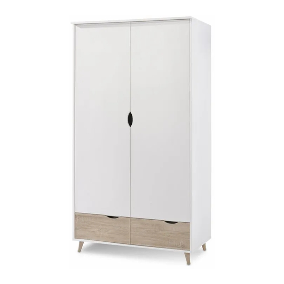
LPD STOCKHOLM 2 DOOR 2 DRAWER WARDROBE
Assembly Instructions - Please keep for future reference
PLEASE KEEP THE ORIGINAL PACKAGING UNTIL THE ITEM IS FULLY ASSEMBLED AND IN PLACE.
IN THE UNLIKELY EVENT THAT YOU NEED TO RETURN YOUR PRODUCT, IT MUST BE RETURNED IN
ITS ORIGINAL PACKAGING TO AVOID FURTHER DAMAGE. FAILURE TO COMPLY TO THESE
PROCEDURES, NO RETURN'S WILL BE ACCEPTED.
1 Hour
190CM
1
Advertisement

Related Manuals for Archers Sleepcentre LPD STOCKHOLM


Summary of Contents for Archers Sleepcentre LPD STOCKHOLM
- Page 1 LPD STOCKHOLM 2 DOOR 2 DRAWER WARDROBE Assembly Instructions - Please keep for future reference PLEASE KEEP THE ORIGINAL PACKAGING UNTIL THE ITEM IS FULLY ASSEMBLED AND IN PLACE. IN THE UNLIKELY EVENT THAT YOU NEED TO RETURN YOUR PRODUCT, IT MUST BE RETURNED IN ITS ORIGINAL PACKAGING TO AVOID FURTHER DAMAGE.
-
Page 2: Exploded View
Exploded View Components - Panels Please check that you have all the components listed below before constructing your items. Parts No Description Side Panel - L Side Panel - R Top Support Panel Top Shelf Panel Center Panel Top Panel Door Panel - L Door Panel - R Drawer Side Panel - L... -
Page 3: Components - Fixings
COmponents - Fixings Please check that you have all the components listed below before constructing your items. Note: The quantities below are the correct amount to complete the assembly. In some cases more fittings may be supplied than are required Wood Dowel 8 x 30mm CB Screw 4 x 38mm Cam Bolt... - Page 4 Assembly Instructions Step 1 C x 8 Step 2 C x 12 Step 3 C x 12...
- Page 5 Step 4 B x 12 Step 5 B x 12...
- Page 6 Step 6 J x 4 Step 7 J x 8 Step 8 J x 7...
- Page 7 Step 9 Q x 2 M x 1 R x 4 2nd Hole 2nd Last Hole Step 10 R View L View M x 1 R x 4 2nd Hole 2nd Last Hole Step 11 D x 2...
- Page 8 Step 12 V x 6 10mm 10mm Step 13 D x 2 E x 4 Step 14 F x 12 P x 6 L View R View...
- Page 9 Step 15 B x 4 Step 16 C x 8 J x 4 (x2) Step 17 A x 8 (x2)
- Page 10 Step 18 (x2) Step 19 1st Step 2nd Step Step 20 N x 2 H x 8 (x2)
- Page 11 Step 21 1st Step 2nd Step Rear View Step 22 G x 2 1st Step 2nd Step Rear View...
- Page 12 Step 23 G x 2 1st Step 2nd Step Rear View Step 24 D x 6 Rear View...
- Page 13 Step 25 G x 4 1st Step 2nd Step Rear View Step 26 O x 40 H x 4 PLEASE ENSURE THAT EACH OF THE FOUR CORNERS OF THE CABINET IS SQUARE...
- Page 14 Step 27 I x 1 Step 28 F x 6 A. Lateral adjustment by screw adjusting B. Vertical adjustment via slot in the mounting plate L View C. Front to back by the slacking the hinge arm mounting screw...
- Page 15 Step 29 F x 6 A. Lateral adjustment by screw adjusting B. Vertical adjustment via slot in the mounting plate C. Front to back by the slacking the hinge arm R View mounting screw Step 30...
-
Page 16: Hardware List
FITTING OF ANTI-TIP SAFETY STRAP STEP 1: M4 x 25mm Pull the screw in the top panel hole of your furniture STEP 2: Make a hole on the wall and pull Wall Plug the wall plug in STEP 3: Pull the screw in M4 x 38mm the wall plug hole HARDWARE LIST...
Need help?
Do you have a question about the LPD STOCKHOLM and is the answer not in the manual?
Questions and answers