Table of Contents
Advertisement
Quick Links
Advertisement
Table of Contents

Related Manuals for Bosch ETT 6.21


Summary of Contents for Bosch ETT 6.21
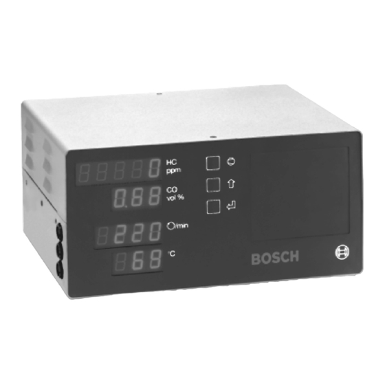
- Page 1 Operating Instructions Illustration ETT 6.22 Exhaust-gas analyser ETT 6.21 / 6.22...
- Page 2 Bosch - Test Technology Certified Quality-Management-Systems according to DIN EN ISO 9001 by: Reg. Nr.: 4066-01 Reg. Nr.: Z-1037-17...
-
Page 3: Table Of Contents
Checking the stability of the readings Checking the flow monitoring system Before switching off the instrument Scope of delivery 10.1 Scope of delivery ETT 6.21 10.2 Scope of delivery ETT 6.22 Special accessories Spare parts, parts subject to wear, special accessories... -
Page 4: Instructions For Your Personal Safety And For The Protection Of Equipment/Vehicle Components
Instructions for your personal safety and for the protection of equipment/vehicle components Mains voltages Danger of acid burning in the respiratory system High voltage Hazardous voltages occur in both the lighting system and the When exhaust gas measurements are taken, the sam- electrical system of a motor vehicle. - Page 5 Danger of asphyxiation Danger of burning Car exhaust fumes contain carbon monoxide (CO) - a colorless, When working on a hot engine, there is a risk of injury from odorless gas. If inhaled, carbon monoxide causes an oxygen burning if such components as the exhaust gas manifold, the deficiency in the body.
-
Page 6: General Information
2.3 Who it is made for The ETT 6.21 / 6.22 has been built for trained expert personnel in the automotive sector. In order to ensure your own safety and to prevent damage to the equipment as a result of improper use, please read the information in these Operating Instructions carefully. -
Page 7: Views And Controls
3.2 Views and controls vol % /min 459667K °C BOSCH Fig. 3 Fig. 3 Fig. 3 Fig. 3 Fig. 3, Side view of ETT 6.22 / Sensor connection diagram: 459665K Jack for inductive trigger clamp-on pickup Jack for term. 1, TD/TN, B- or vehicle earth Jack for oil-temperature sensor Fig. -
Page 8: Exhaust-Gas Measurements On 2-Stroke Engines
HC measurement is corrupted (increased). BOSCH Made in USA This effect, referred to as “hang-up” in specialist circles, occurs with all exhaust-gas measuring instruments irrespective of make. -
Page 9: Exhaust Analysis
(ETT 6.22 only) – sampling probe (damage, clogging) Engine-speed and oil-temperature measurement not inte- – filter (fitted, damage) grated (ETT 6.21) – sampling hose (damage, clogging) – filters GF1, GF3 and GF4 – coarse filter (GF2) in the water separator The EEPROM status is displayed. - Page 10 After this, the warm-up phase is counted down. The duration of 4.1.3 Leak test the warm-up phase depends on the status of the instrument and it can last up to approx. 6 minutes. Danger! Hot parts! b 0 5 C H The sampling probe can become very hot depending on the length of the exhaust-gas measurement.
-
Page 11: Prerequisites For An Exhaust-Gas Measurement
– Push the grommet up or down the oil-temperature sensor If this does not solve the problem, contact your Bosch After-Sales (special accessory) so that it has the same length as the oil Service representative and quote the error message displayed. -
Page 12: Exhaust-Gas Measurement
(3) pressed, the instrument automatically testing station) are entered W 33678 New Hattanham switches to pause mode. by Bosch After-Sales Fast Drive 23B Service. Phone: 03456-555-888 – Insert the sampling probe (19) into the tail pipe or into the... -
Page 13: Entry Menus
5. Entry menus 5.2.1 Zero adjustment The entry menus can be used to call up and check various This submenu option can be used to carry out zero adjustment. functions of the exhaust-gas measuring instrument. To perform zero adjustment, the measuring instrument switches a solenoid-operated valve over to ambient air. - Page 14 Zero adjustment is then performed. After the HC residue test has been completed, either the mes- sage PA55 or FA1L is displayed. The exhaust-gas measuring instrument the automatically returns to the user menu. 5.2.3 Display of HC sum factor This submenu option can be used to dislay th HC sum factor.
-
Page 15: Engine-Speed Measurement (Ett 6.22 Only)
6. Engine-speed measurement (ETT 6.22 only) 6.3 Setting the number of pulses 6.1 Connecting the sensors to the exhaust-gas analyser The number of pulses is set in the user menu (see section 5.2) under the submenu option PUL5E. On the side of the unit are 3 plug-in sockets. The sensors for measuring the engine-speed are connected to the plug-in sok- P U L 5 E kets 23 and 24. - Page 16 6.3.1 Number of pulses and type of ignition The number of pulses per 720° revolution of the crankshaft depends on various factors: During engine-speed measurement, the number of pulses for 2 revolutions of the crankshaft (720°) is evaluated. These pulses –...
- Page 17 6.3.2 Measuring point (Item 1): Secondary side, ignition cable between distributor and spark plug of any cylinder (one ignition circuit) (Item 2): Secondary side, ignition cable between ignition coil and distribu- tor (terminal 4, all ignition circuits) (Item 3 or 4): Primary side, term.
-
Page 18: Special Accessories
7. Special accessories 7.1.2 Changing the printer ribbon 7.1 Protocol printer When the exhaust-gas analyser is switched on a protocol can be 459511P printed out on the protocol printer (6) showing the following details: – a protocol according to the parametrization (see section 5.3.15) –... -
Page 19: Error Messages And Information Messages
Restart measurement by pressing the E key (5) twice. your Bosch After-Sales Service representative and quote the code number(s). If this does not remedy the problem, contact your Bosch After- Sales Service representative and quote the information message. Error 600... -
Page 20: Messages In The Engine-Speed Display
If this does not remedy the problem, contact your Bosch After- – Renewal of protective filter GF5 and zero-gas filter GF6. Sales Service representative. – If necessary, renewal of activated charcoal filter in zero-gas path. -
Page 21: Filter Gf1
The pump is switched off after 30 s. 459666/1K If this message is not displayed, there is a fault in the flow monitoring system. Contact your Bosch After-Sales Service representative and have him send someone to search for and repair the fault. -
Page 22: Scope Of Delivery
10. Scope of delivery 11. Special accessories 10.1 Scope of delivery ETT 6.21 Designation Part number – ETT 6.21 basic unit Protocol printer PDR 078 1 687 023 078 – Exhaust-gas sampling probe, 500 mm long – Test jack for leak test Installation kit for protocol printer PDR 078 1 687 001 264 –... -
Page 23: Technical Data
13. Technical Data Analysis Measurement range Resolution HC measurement range 0 - 2000 ppm vol HC 1 ppm vol 2000 - 20000 ppm vol HC 10 ppm vol CO measurement range 0.00 - 9.99 % vol CO 0.01 % vol Engine-speed measurement 0 - 9990 U/min... - Page 24 ETT 6.21 0 684 100 621 ETT 6.22 0 684 100 622 Robert Bosch GmbH Geschäftsbereich Automationstechnik Prüftechnik Postfach 1129 D 73201 Plochingen...
Need help?
Do you have a question about the ETT 6.21 and is the answer not in the manual?
Questions and answers