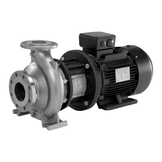
Grundfos NB Original Installation And Operating Instructions
Hide thumbs
Also See for NB:
- Installation manual ,
- Installation and operating instructions manual (240 pages) ,
- Instructions manual (108 pages)
Table of Contents
Advertisement
Quick Links
Original installation and operating instructions.
CONTENTS
1.
Symbols used in this document - 6
2.
General information - 6
3.
3.1
Delivery - 7
3.2
Handling - 7
4.
Type keys - 8
4.1
Type NB - 8
4.2
Type NBG - 8
4.3
Impeller diameter - 10
4.4
Pumped liquids - 10
5.
Technical data - 10
5.1
Ambient temperature - 10
5.2
Liquid temperature - 10
5.3
Operating pressure - 10
5.4
Min. inlet pressure - 10
5.5
5.6
Minimum flow rate - 10
5.7
Maximum flow rate - 10
5.8
Electrical data - 10
5.9
Weight - 10
5.10
Sound level - 10
5.11
6.
Pump without motor - 11
6.1
Motor without feet - 11
6.2
Motor with feet - 13
7.
7.1
7.2
Pump location - 15
7.3
Connection - 15
7.4
7.5
7.6
Pipework - 20
7.7
Vibration dampening - 20
7.8
Expansion joints - 21
7.9
8.
9.
9.1
Motor protection - 23
9.2
10.
Start-up - 24
10.1
General information - 24
10.2
Priming - 24
10.3
10.4
Start-up - 24
10.5
Start/stop - 24
11.
Maintenance - 25
11.1
Pump - 25
11.2
11.3
Motor - 25
11.4
Lubrication - 25
12.
13.
Service - 25
13.1
Service kits - 25
14.
15.
Fault finding chart - 26
16.
Disposal - 26
Warning
Prior to installation, read these installation and
operating instructions. Installation and operation
must comply with local regulations and accepted
codes of good practice.
6
1. Symbols used in this document
Warning
If these safety instructions are not observed,
it may result in personal injury!
If these safety instructions are not observed,
it may result in malfunction or damage to the
Caution
equipment!
Notes or instructions that make the job easier
Note
and ensure safe operation.
2. General information
Pump type and model are stated on the pump nameplate
The pumps are fitted with Grundfos motors, type MG or MMG. If
the pump is fitted with a motor make other than Grundfos, please
note that the motor data may differ from the data stated in this
booklet. This may also influence the pump performance.
Advertisement
Table of Contents

Related Manuals for Grundfos NB


Summary of Contents for Grundfos NB
-
Page 1: Table Of Contents
Pump type and model are stated on the pump nameplate Liquid temperature - 10 The pumps are fitted with Grundfos motors, type MG or MMG. If Operating pressure - 10 the pump is fitted with a motor make other than Grundfos, please Min. -
Page 2: Delivery And Handling
Test certificates are available from Grundfos. The pumps are delivered from the factory in a carton with a wooden bottom designed for transport by equipment such as a forklift truck. -
Page 3: Type Keys
BAQE shaft seal and a 4-pole motor. Fig. 4 Example of nameplate for NB The example shows an NB 80-200 with 196 mm impeller, made of cast iron with BAQE shaft seal and a 4-pole motor. - Page 4 Mechanical shaft seal 28, 38 Temperature Shaft seal diameter [mm] Code Maximum pressure range [bar] Rubber bellows seal, metal-impregnated carbon/silicon carbide, BAQE 0 °C to +120 °C EPDM Rubber bellows seal, metal-impregnated carbon/silicon carbide, BAQV 0 °C to +90 °C Rubber bellows seal, silicon carbide/silicon carbide, EPDM BQQE 0 °C to +90 °C...
-
Page 5: Impeller Diameter
The flow rate and head are stated on the pump of glycol-containing liquids. nameplate. For heating systems, the water quality should meet VDI 2035. Contact Grundfos for further information. 5.7 Maximum flow rate The maximum flow rate must not exceed the values stated for the 5. Technical data individual pump on page 585, as otherwise there is a risk of for instance cavitation and overload. -
Page 6: Pump Without Motor
6. Pump without motor 6.1 Motor without feet NB and NBG pumps are available without motor. The pumps are supplied as complete pumps with a transport bracket protecting the shaft seal during transport. When you mount the motor, follow the instructions shown in these drawings. - Page 7 5. Press down the threaded pipe to ensure that the shaft is in 6. Remove the threaded pipe. bottom position. 7. Apply Loctite 243 to the threads of the hexagon socket 8. Fit the coupling guard. Tighten the screws to the correct screws.
-
Page 8: Motor With Feet
6.2 Motor with feet NB and NBG pumps are available without motor. The pumps are supplied as complete pumps with a transport bracket protecting the shaft seal during transport. When you mount the motor, follow the instructions shown in these drawings. - Page 9 5. Press down the threaded pipe to ensure that the shaft is in 6. Remove the threaded pipe. bottom position. 7. Apply Loctite 243 to the threads of the hexagon socket 8. Fit the coupling guard.Tighten the screws to the correct screws.
-
Page 10: Mechanical Installation
1 metre clearance above the motor to allow the use of lifting equipment. • NB pumps with base frame must have the same clearance as pumps with motors from 5.5 to 200 kW. -
Page 11: Foundation Of Nb, Nbg Pump Without Base Frame
7.4 Foundation of NB, NBG pump without base frame 7.5 Foundation of NB, NBG pump with base frame This section applies only to 50 Hz pumps, as base frames are not The foundation/installation must be carried out in supplied for 60 Hz pumps. - Page 12 NB, NBG pumps with base frame are always prepared for grouting (grouting anchors welded on to the base frame). For 2-pole NB, NBG pumps with large motors, grouting of the base frame is mandatory in order to prevent vibration energy from the rotating motor and liquid flow to evolve.
- Page 13 1: Pouring of foundation We recommend the following procedure to ensure a good foundation. Step Action Illustration Use an approved, non-shrinking concrete. (Contact your concrete supplier for advice if any doubts.) Pour the foundation without interruptions to within 19 to 32 mm of the final level.
- Page 14 3: Grouting Grouting compensates for uneven foundation, distributes weight of unit, dampens vibrations and prevents shifting. Use an approved, non-shrinking grout. If you have questions or doubts about the grouting, please contact an expert on grouting. Step Action Illustration Min. 20 bars Embed reinforcing steel bars into the foundation by means of 2K anchor adhesive glue.
-
Page 15: Pipework
7.6 Pipework 7.6.3 Bypass 7.6.1 Piping Warning When installing the pipes, make sure that the pump housing is The pump is not allowed to run against a closed not stressed by the pipework. valve as this will cause an increase in temperature/formation of steam in the pump The suction and discharge pipes must be of an adequate size, which may cause damage to the pump. -
Page 16: Expansion Joints
When measuring with pressure gauges on the pump flanges, it should be noted that a pressure gauge does not register dynamic pressure (velocity pressure). On all NB pumps, the diameters of the suction and discharge flanges are different which results in different flow velocities at the two flanges. -
Page 17: Flange Forces And Torques
* Σ F and Σ M are the vector sums of the forces and torques. If not all loads reach the maximum permissible value, one of the values is allowed to exceed the normal limit. Contact Grundfos for further information. -
Page 18: Electrical Connection
Cable length circuit breaker. (The length of the cable between motor and All three-phase Grundfos MG and MMG motors of 3 kW and up frequency converter affects the motor load.) incorporate a thermistor. See the instructions in the motor Supply voltage up Check that the motor is suitable for terminal box. -
Page 19: Start-Up
10. Start-up 10.3 Checking the direction of rotation Warning Do not start the pump until it has been filled with Note liquid and vented. The pump must be filled with liquid when checking the direction of rotation. 10.1 General information The correct direction of rotation is shown by arrows on the pump housing. -
Page 20: Maintenance
If Grundfos is requested to service the pump, Grundfos must be 11.1 Pump contacted with details about the pumped liquid, etc. before the The pump is maintenance-free. -
Page 21: Fault Finding Chart
Reduce the flow rate. 16. Disposal This product or parts of it must be disposed of in an 2. If this is not possible, contact the nearest Grundfos company environmentally sound way: or service workshop. 1. Use the public or private waste collection service.
Need help?
Do you have a question about the NB and is the answer not in the manual?
Questions and answers