
Related Manuals for AMOT C


Summary of Contents for AMOT C
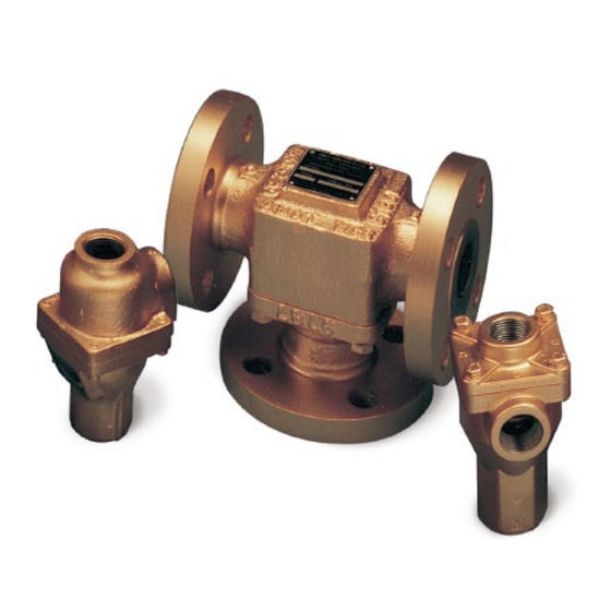
- Page 1 Model C Valve Thermostatic valve for diverting and mixing applications Installation, Operation and Maintenance Manual Doc No: OMMC00296 Revision: 2 – Sept 2020...
- Page 2 Original instructions...
-
Page 3: Table Of Contents
Table of Contents Section 1 Table of Contents Section 1 ..................3 Section 2 ..................5 Scope .................. 5 Safety ................. 5 Product support ..............5 Section 3 ..................7 Overview ................7 3.1.1 Manual override ............. 7 Features ................7 Valve Selection .............. - Page 4 Table of Contents Revision: 2 – Sept 2020 OMMC00296...
-
Page 5: Section 1
Introduction 2.1 Scope This manual details the installation, operation and maintenance of the AMOT Model C Valve range. 2.2 Safety Certain operations within this manual are potentially hazardous and could cause injury to personnel or damage to equipment if the instructions are not carried exactly as described. - Page 6 Introduction Revision: 2 – Sept 2020 OMMC00296...
-
Page 7: Section 3
Section 3 Description 3.1 Overview The Model C Valve is designed to provide fully automatic, 3-way fluid temperature control for diverting or mixing applications. Typical applications include engine water jackets, lubricating oil cooling systems, and mixing and diverting of fluids in process control and industrial applications. -
Page 8: Valve Selection
3.3 Valve Selection A wide range of valve sizes and materials of construction are available, covering the applications in Section 3.2. An AMOT C Valve datasheet containing information on selection of the appropriate valve type is available, contact AMOT for a copy. -
Page 9: Identification Of Model Number
-*** Customer special code assigned Table 1– Model Identification *Note: Leakhole quantity character is not used for CM, CL, CF type valves, only Other Flange connections are available. Contact AMOT for details. Doc No: OMMC00296 Revision: 2 – Sept 2020... - Page 10 Description Rated Range Control Max Temp Max Temp Temp Continuous Short Period Code Crack Open Full Open °C °F °C °F °C °F °C °F °C °F Table 2 – Element Temperatures Revision: 2 – Sept 2020 OMMC00296...
- Page 11 Nickel plated 10765P CM/CCM/CF 9778C Neoprene Nickel plated 10765K CM/CCM/CF Salt water – FKM (Viton) 44844X Stainless steel Table 3 – Element/Seal Types Other Elements and Seals are available. Contact AMOT for details. Doc No: OMMC00296 Revision: 2 – Sept 2020...
- Page 12 Description Revision: 2 – Sept 2020 OMMC00296...
-
Page 13: Section 4
Pressure Accessory under the terms of the EU Pressure Equipment Directive (PED). The Model C Valve, when suitable for use within the European Community, carries a nameplate, an example of which is shown in Figure 1. The nameplate contains the following information pertinent to the Pressure Equipment Directive requirements: Figure 1 –... -
Page 14: Hazardous Areas
The Model C Valve has been assessed for use in places designated as containing hazardous gas; they shall not be used in places designated as containing hazardous dust. - Page 15 Notified Body (per Technical File ref. above). Equipment that is CE marked must comply with all relevant EU Directives. The CE mark on the AMOT C Valve only represents compliance to the ATEX Directive and not to other EU Directives.
-
Page 16: Specific Conditions Of Use
4.3 Machinery Directive The Model C Valve supplied by AMOT is classified as a component. The equipment falls outside the scope of the machinery directive. Components are only intended to be incorporated into or assembled with other machinery or equipment thereby forming Machinery. -
Page 17: Section 5
5.1 Installing the valve 5.1.1 Before starting installation 1. Upon receipt, the valve should be checked for damage sustained in shipping. All AMOT valves have nameplates attached, which are stamped with the valve model number and serial number. 2. Understand the intended use of the valve as described in Section 3. -
Page 18: Mounting The Valve In The Pipe
2.7°C (5°F) from the nominal temperature, then effort should made to locate the cause. Any system operating at an indicated 5.5°C (10°F) or more from the nominal anticipated temperatures may well be malfunctioning and the cause should be located and rectified immediately. See trouble- shooting section for possible causes. -
Page 19: Section 6
6.1.2 Mixing applications (controls inlet temp to load source) When valves are used for mixing service, Port C is the cold fluid inlet port from the cooler, Port B is the hot by-pass fluid inlet, and Port A the common outlet. Port A is the temperature sensing port and will mix the hot and cold fluids in the correct proportion so as to produce the desired outlet temperature leaving Port A. -
Page 20: 2-Way Water Saving Applications
Operation 6.1.3 2-way Water Saving Applications Valve as shown maintains minimum flow through cooler to conserve water. Requires an internal leak hole to permit a small flow for sensing. Revision: 2 – Sept 2020 OMMC00296... -
Page 21: Section 7
To obtain maximum service life from the valve, periodic inspection and cleaning should be incorporated into a normal preventative maintenance program. Properly applied and installed AMOT thermostatic valves require minimal maintenance. Inspection at 2 year intervals is adequate to detect normal wear. -
Page 22: Dismantling The Valve
Maintenance 7.1 Dismantling the valve Figure 2 - Cross Sectional View, Types CL/CM A/R/S Revision: 2 – Sept 2020 OMMC00296... - Page 23 Maintenance Figure 3 - Cross Sectional View, Other Types Doc No: OMMC00296 Revision: 2 – Sept 2020...
-
Page 24: Reassembling The Valve
(Item 9). Inspect valve internals for wear or damage. Worn or damaged valves must not be returned to service. Where required, contact AMOT for a replacement valve. For all other valve types: Refer to Figure 3. Remove housing nuts (Item 12) or screws (Item 13) and split the valve. - Page 25 Maintenance For all other valve types: Refer to Figure 3. Lightly grease replacement element seal(s) (Item 7) and locate in upper housing (Item 1). Replace element (Item 8) into valve, ensuring it is centrally located. Lightly grease replacement ‘O’ ring (Item 9) and fit into upper housing (Item 1) recess.
-
Page 26: User Maintenance Parts
44844X(°F) Element assembly, ‘Saltwater’ plated Table 5 – Element assembly part numbers Other Elements are available. Contact AMOT for details. See Table 1, “Element Type” row. Table 6 gives the part numbers for spare seal kits, containing the required seals for the models shown. Kits include Items 7 & 9, and 10, where required. -
Page 27: Section 8
Trouble shooting Section 8 Trouble shooting In the event that the cooling system does not operate close to the desired temperature, the following guide may help to identify or locate the problem. 8.1 System temperature too cold 1. Insufficient heat rejected to coolant to maintain temperature. 2. - Page 28 Trouble shooting Revision: 2 – Sept 2020 OMMC00296...
-
Page 29: Section 9
Technical Specification Section 9 Technical Specification 9.1 General valve specification 9.1.1 Materials Body materials ........... Aluminium, Bronze, Cast Iron, Steel, Stainless steel Internal materials (elements) ......Stainless Steel and Bronze Option: Nickel plating Seal material ........Buna Nitrile, FKM (Viton), Neoprene 9.1.2 Maximum working pressure Type Max working pressure... -
Page 30: Valve Handling
(refer to Section 9.1.3). Storage is permitted down to -40°C (-40°F) for valves containing Nitrile, EPDM, Neoprene ‘O’ rings and down to -26°C (-14.8°F) for valves containing FKM (Viton) ‘O’ rings but this must be followed by a slow increase of no higher than 1°C per minute. - Page 31 Technical Specification Doc No: OMMC00296 Revision: 2 – Sept 2020...
- Page 32 +44 (0) 1284 762222 Fax: +1 (713) 559 9419 Fax: +44 (0) 1284 760256 Email: sales@amotusa.com Email: info@amot.com AMOT Controls GmbH Rondenbarg 25 22525 Hamburg Germany Asia and Australasia Tel: +49 (0) 40 8537 1298 AMOT Shanghai Tel: +49 (0) 40 8537 1331 Bd.
Need help?
Do you have a question about the C and is the answer not in the manual?
Questions and answers